diy solar

diy solar

JK BMS CAN bus comms now possible for inverters that support Goodwe and Pylontech batteries

If you do a lot of change and testing with Wire and BLE. Sometimes it is necessary to remove your ESP32 from HA in order to remove all entities and then import it again.
Yes i have been doing that - especially when i swapped the esp32 knowing the IP would change thanks for the reminder
 
the below section is missing from the Wire so i cannot pick a protocol version

# Please use "JK02_24S" if you own a old JK-BMS < hardware version 11.0 (hardware version >= 6.0 and < 11.0)
# Please use "JK02_32S" if you own a new JK-BMS >= hardware version 11.0 (f.e. JK-B2A8S20P hw 11.XW, sw 11.26)
# Please use "JK04" if you have some old JK-BMS <= hardware version 3.0 (f.e. JK-B2A16S hw 3.0, sw. 3.3.0)
protocol_version: JK02_32S
mac_address: C8:47:80:08:20:D0
 
@chaosnature

In the future, please take the time to read, understand and properly configure YAML.

The Wire and BLE version are used by other people without problems and also with Solis.

You have to take your time and not try 10,000 things at once. Step by step.

Concerning the Wire version I don't know what's going on, you have to check your entire configuration at your ease starting with the wiring. If you follow the README and your hardware is OK then it should work.

I must leave you now.
 
How to combine the both Growatt GBLI5001 batteries is the next challenge for me :)
Is this your battery?

Did you replace the BMS with JK-BMS?

How to combine the both Growatt GBLI5001 batteries is the next challenge for me :)
 
@chaosnature

In the future, please take the time to read, understand and properly configure YAML.

The Wire and BLE version are used by other people without problems and also with Solis.

You have to take your time and not try 10,000 things at once. Step by step.

Concerning the Wire version I don't know what's going on, you have to check your entire configuration at your ease starting with the wiring. If you follow the README and your hardware is OK then it should work.

I must leave you now.
Copy that...

many thanks for your help...apologies for taking your time

regards
 
Same, I bought a Victron smartshunt late last week for this exact reason.
I intend to design a PCB with:

- ESP32 module
- RJ45 connector
- JK BMS connector
- Smartshunt connector
- Relay (for heater, etc)
- Spare GPIO breakout
- Isolated power from JK BMS

All in a 3d printed housing.
If / when I get it done, I'll share the PCB design files, etc, on GitHub for others.
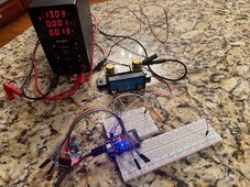
Bought a few things and hooked up my Victron SmartShunt and got this running based on this fork: https://github.com/sijones/VE.DirectMQTTCANBUS
I'm not sure the pins to the MCP2515 CAN Bus board are correct. Had to tweak a few things, but it is reading from the shunt. Also have it set via MQTT in HA.

Code:
[ 13881][I][CANBUS.cpp:304] SendParamUpdate(): Sent PYLONTECH String.
[ 13886][I][CANBUS.cpp:333] SendParamUpdate(): Inverter Parameters update via CAN Bus sent.
[ 13890][I][CANBUS.cpp:138] SendBattUpdate(): Inverter SOC Battery update via CAN Bus sent.
[ 13902][I][CANBUS.cpp:160] SendBattUpdate(): Inverter Battery Voltage, Current update via CAN Bus sent.
[ 13912][I][CANBUS.cpp:182] SendBattUpdate(): Inverter Protection / Alarm Flags via CAN Bus sent.
[ 13920][I][CANBUS.cpp:205] SendBattUpdate(): Battery Charge Flags via CAN Bus sent.
[ 13945][I][main.cpp:190] loop(): New block arrived; Value count: 13, serial 26
[ 13946][I][main.cpp:113] UpdateCanBusData(): Battery Voltage Update: 12625V
[ 13948][I][main.cpp:119] UpdateCanBusData(): Battery Current Update: 0mA
[ 13955][I][main.cpp:125] UpdateCanBusData(): Battery SOC Update: 1000%
[ 14445][I][main.cpp:190] loop(): New block arrived; Value count: 17, serial 27
[ 14928][I][CANBUS.cpp:60] SendAllUpdates(): Sending all CAN Bus Data
[ 14929][I][CANBUS.cpp:304] SendParamUpdate(): Sent PYLONTECH String.
[ 14934][I][CANBUS.cpp:333] SendParamUpdate(): Inverter Parameters update via CAN Bus sent.
[ 14938][I][CANBUS.cpp:138] SendBattUpdate(): Inverter SOC Battery update via CAN Bus sent.
[ 14947][I][main.cpp:190] loop(): New block arrived; Value count: 13, serial 28
[ 14950][I][CANBUS.cpp:160] SendBattUpdate(): Inverter Battery Voltage, Current update via CAN Bus sent.
[ 14962][I][main.cpp:113] UpdateCanBusData(): Battery Voltage Update: 12625V
[ 14967][I][CANBUS.cpp:182] SendBattUpdate(): Inverter Protection / Alarm Flags via CAN Bus sent.
[ 14978][I][main.cpp:119] UpdateCanBusData(): Battery Current Update: 0mA
[ 14982][I][CANBUS.cpp:205] SendBattUpdate(): Battery Charge Flags via CAN Bus sent.
[ 14992][

IMG_4648.jpeg

 
Last edited:
Same, I bought a Victron smartshunt late last week for this exact reason.
I intend to design a PCB with:

- ESP32 module
- RJ45 connector
- JK BMS connector
- Smartshunt connector
- Relay (for heater, etc)
- Spare GPIO breakout
- Isolated power from JK BMS

All in a 3d printed housing.
If / when I get it done, I'll share the PCB design files, etc, on GitHub for others.

These are great ideas 😍

I notified you in the following discussion :
Solving the wrong calculation of SOC on JK-BMS board

Adding a shunt as a source in addition to JK-BMS was part of my todo list.

But after hesitating for a long time between Victron and Junctek, I bought a Junctek KH-F 140 shunt (good quality/price ratio) and I started its integration into HA with ESPHome. I would have the shunt with me during my 4 months in Portugal. We could begin the integration of Victron / Junctek shunts.
 
Last edited:
Same, I bought a Victron smartshunt late last week for this exact reason.
I intend to design a PCB with:

- ESP32 module
- RJ45 connector
- JK BMS connector
- Smartshunt connector
- Relay (for heater, etc)
- Spare GPIO breakout
- Isolated power from JK BMS

All in a 3d printed housing.
If / when I get it done, I'll share the PCB design files, etc, on GitHub for others.

Very cool!

I'm working on something similar but would like to add a display to this "all-in-one box" for real-time monitoring of main parameters (SoC, voltage, current, charging status..)
This way, the JK-CAN-BMS SW will serve a dual purpose: protocol conversion/adaptation for JK-BMS and real-time monitoring
 
Hi Guys - It's me again Chaosnature :)

this is a quick one

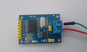
would the below work in place of the CAN conversion replacing the other TJA1050

I can figure out the :
VCC, GND the CAN-H and the CAN-L

just the tx and the tr I am not sure of
1708435315159.png


Or does this only work for Arduino? its still a TJA1050 receiver
 
Hi Guys - It's me again Chaosnature :)

this is a quick one

would the below work in place of the CAN conversion replacing the other TJA1050

I can figure out the :
VCC, GND the CAN-H and the CAN-L

just the tx and the tr I am not sure of
View attachment 197026


Or does this only work for Arduino? its still a TJA1050 receiver
This module is a SPI module, so it doesn't use the standard UART TX and RX that is recommended for this project.
There is more information within the ESPhome documentation here on how to use this, but I'd recommend using a non-SPI CAN module.
 
The above device is the exact module for the Victron/ESP/CAN project I mentioned a few posts above which seems to be working for the other project. Ignoring the BMS completely and providing info from Victron SmartShunt to inverters (regardless of # of batteries behind it).
 
The above device is the exact module for the Victron/ESP/CAN project I mentioned a few posts above which seems to be working for the other project. Ignoring the BMS completely and providing info from Victron SmartShunt to inverters (regardless of # of batteries behind it).
Waow, i wish we can do that with this...
 
Waow, i wish we can do that with this...
Easiest way to do this is to use a 5v usb input to the ESP32 which will provide enough power to the SPI CAN interface. Anyway, I'll probably start another thread on this once I get this working right.

Don't want to dilute the value of this thread. I'm using 1.16.4 still on the M5 atom stack and stable/reporting, not using it for inverter control yet.
 
Last edited:
Similar topic, does anyone know a tool on MacOS and the connectivity to look at the CAN payload before hooking up to inverter?
 
I wonder what everyone did to get the Wire working....i have even gone into the Git repository for fresh code and used 2 different ESP32 variants ....beats me
Can only get the CAN to work
 
Similar topic, does anyone know a tool on MacOS and the connectivity to look at the CAN payload before hooking up to inverter?
Bought this in the hopes to archive what you are planning, not tried it yet...and not sure if it works on MAC

1708452093015.png
 
Back
Top