diy solar

diy solar

JK BMS CAN bus comms now possible for inverters that support Goodwe and Pylontech batteries

i have a question/discussion

So we should see current flow like water, right?
Water always finds its level
So storage charges should also find their level right?
 
Should this not mean if we have say for example a battery level to say 90%
and then we have another that is 50%
if we connect them in parallel current should flow from the 90 to the 50 to level it up

Let's call it Passive sleep mode balancing...if that's correct
 
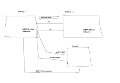
1708453128039.png

Then why can't we have the above??

Just a simplified thought - don't bite me :)

# Question is mainly to the developers who already know some Maths to this

# and to any other technical-minded person out there on these kind of projects

Note: this is a High-Level Design.
in more detail, the Batt 2 wires actually connect to the Batt 1 before the BMS terminals....
I would install a breaker switch between them.
 
Last edited:
One thing that comes to mind is, that both Batt, especially Batt-1 will be discharging and re-charging more often,
but then that is what the cells do when they balance themselves using the active balancers. so the cell life in terms of cycle per age would still not matter....

And with a setup like this, I would imagine it will not require much update to the existing code to get them synchronized and working perfectly like happy couples :)

and by the way, the JKBMS P- of the second Batt will not be connected in this case - the BMS would just do the job of balancing

We just have to consider adding up the amperage - to not go over the BMS's amperage rating.
 
Last edited:
I wonder what everyone did to get the Wire working....i have even gone into the Git repository for fresh code and used 2 different ESP32 variants ....beats me
Can only get the CAN to work
Try swapping the rx and Tx pin definitions in the original code
GPIO16 and 17. It should work
 
Try swapping the rx and Tx pin definitions in the original code
GPIO16 and 17. It should work
I thought i saw a thread where UKsa said he fixed it...

will it not just mean simply switching the cables around - save me from reflashing?
 
I thought i saw a thread where UKsa said he fixed it...

will it not just mean simply switching the cables around - save me from reflashing?
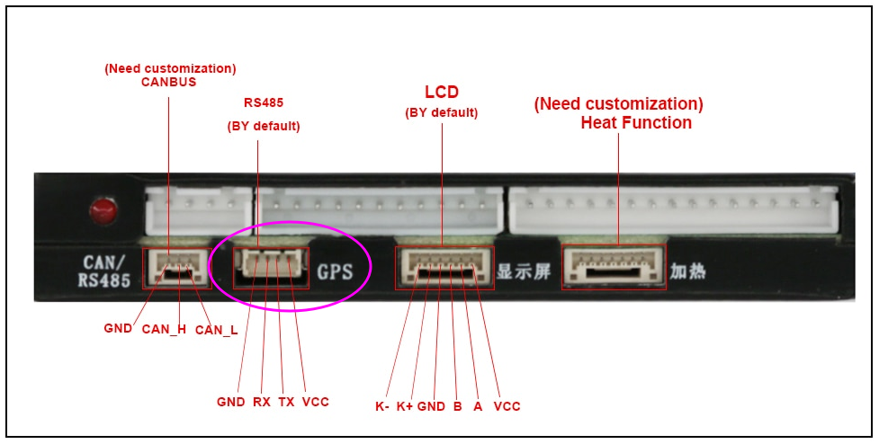
@chaosnature, when you reference the diagram, exactly which gpio pin (as per the physical ESP32 board you have) does RX and TX connect to?

JK-BMS_24S_GPS_port.png


If, for example, the RX pin on the BMS connects to GPIO 16 on your ESP32, ensure that rx_pin in the YAML file matches exactly. Do the same for tx_pin, plus ensure that ground is connected correctly.
That is exactly what i have done - i have just double-checked now

Side note:
On Previous Code i have been able to connect to the PC software after pressing the EN button on the ESP32 chip

i am retrying this again now will send result when i succeed
 
Should this not mean if we have say for example a battery level to say 90%
and then we have another that is 50%
if we connect them in parallel current should flow from the 90 to the 50 to level it up

Let's call it Passive sleep mode balancing...if that's correct

Yes it will balance to a certain point but not as perfectly or quickly as water.

At first it will go very quickly then it will slow down when the voltages of the two batteries are similar.

We can have one cell at 3.29v at 50% and another cell at 3.32v at 70%. The smaller the voltage difference, the longer it will take.
So the concept should work with the JKBMS active balance in play...
 
Bought this in the hopes to archive what you are planning, not tried it yet...and not sure if it works on MAC

View attachment 197074
Does anyone know if this device will capture CANBUS on a PC or MAC and how. I ordered it because it was cheap and could get it in a few hours on amazon, but on MAC or PC, struggling getting it to capture data coming out of CAN. On PC it shows up as a 'candle' device but I can't get any tools such as SavvyCAN or CANGAROO to recognize it.
 
Does anyone know if this device will capture CANBUS on a PC or MAC and how. I ordered it because it was cheap and could get it in a few hours on amazon, but on MAC or PC, struggling getting it to capture data coming out of CAN. On PC it shows up as a 'candle' device but I can't get any tools such as SavvyCAN or CANGAROO to recognize it.
Did you install the drivers?
 
@chaosnature

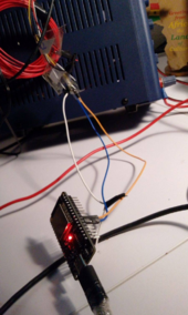
Give us a photo of your setup with the wiring. How the ESP32 is powered etc.

Don't forget to connect ALL GNDs together!
Hello Guys,

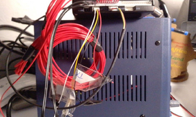
So here are the setup pics

1708622454067.png

This is when i tried GPIO01 and 03 - after flashing the ESP chip with same settings
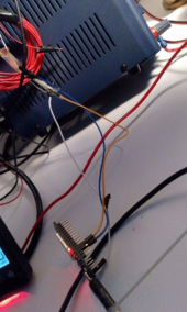
1708622524275.png

This i tried what everyone is using - GPIO16/17 - after flashing the ESP chip

1708622592306.png

The Blue is TX and the yellow is RX the White Ground - Apologies for the mix colours
 
Last edited:
The active balancer has no role to play. If you are charging at 4.1V the Start Balance V. must be set to 4.1V.

FYI @chaosnature used a 14S Li-ion battery!
If we set to start balance @ 4.1 then the Batt 2 cells will be out of balance below that voltage....so i am not sure its best to choose that risk over the proposed 4.1.

also as current is introduced or taken away from Batt 2 (if balancing is set at 3.1 volt which = 43.4 SOC) the BAtt 2 cells gets protected.


if we set at 4.1 doesn't that mean Batt 2 cells will drain out of control anything below 57.4 volts?

by the way generally, what is the recommended Start balance voltage for a 14s like my setup?
 
Did you install the drivers?
Supposedly no drivers needed according to instructions. Should just work on both Mac or PC with 'canact' applicaiton. Nothing works with it. Tried two PC's and two Macs. Can see the device show up in Device Mgr on Windows and System Report on MAC.
 
If we set to start balance @ 4.1 then the Batt 2 cells will be out of balance below that voltage....so i am not sure its best to choose that risk over the proposed 4.1.

also as current is introduced or taken away from Batt 2 (if balancing is set at 3.1 volt which = 43.4 SOC) the BAtt 2 cells gets protected.


if we set at 4.1 doesn't that mean Batt 2 cells will drain out of control anything below 57.4 volts?

by the way generally, what is the recommended Start balance voltage for a 14s like my setup?

Balancing across the entire voltage range is counterproductive. If you want to do top balancing you must do it at the end of the charge. If you charge at 4.1V, we start at 4.1V so top balancing will be done with a low current and will start as soon as max_cell_v reaches 4.1V.

But this is based on my knowledge of LFP.
O.k - Got it...
 
Back
Top