diy solar

diy solar

EG4 6000XP Neutral-Ground Bonding

Search for posts with diagrams from @FilterGuy. There was a line diagram for the 6000xp and a Reliance TS as this is a shared neutral connection. Did your electrician run L1/L2/N/G, all four wires for AC-In?
Sorry Chris, just saw this today (2-6-24 6:36AM) Yes, he did run the 4 wire #6. I have the bare copper wire connected to the 6000XP PE lugs.
 
Can I say this is TRUE:

For all those people that run the 6000xp Off-Grid and use a Chargeverter, disable setting 26 and bond your neutrals and grounds in your (main) AC panel. The End.

Please verify so I can move on.
I saw this was verified as true but I want to verify if charging the batteries with the mppt in the 6000xp this is also true.
 
The reality is, even systems that do dynamic bonding well has to make assumptions about whether there is a bond on the AC in. I do not know of anything on the market that can handle AC-in without bonding sometimes and AC-in with bonding other times. It could be done with modern electronics that detect if a bond exists or not, but I am not aware of any current inverter product with that capability.

So true!!! The 6000XP has a design center of stationary installs. Trying to apply it to mobile is a little bit of a square peg and round hole situation.
Planning totally off grid EV charging and 240V supply to pool heater.
Two EG4 6000XP in parallel to two EG4 PowerPro batteries for 50A 240V supply to an off-grid service panel - grounded to earth ground via continuous 6g copper wire attached to two 8 ft pounded into dirt earth-ground.
There will be NO charging of this system from my house electrical - will only have solar charging (Phoenix, AZ).
I will go to setting #26 in the 6000XP and enable the ground neutral bond.
If I wire a Tesla charger from the off grid service panel, will the Tesla charger show the infamous blinking red error light?
Any experience with this?
I do not have experience with the tesla charger but I do know it has circuitry the checks for the NG bond. As far as I know it should work with your set up.
 
Imo no bond at all is way worse than double bond. My property had a double bond in place for 20 years and in practice the objectionable current just isn't that big a deal.
Old thread but someone revived it and I saw this post so I'm going to input on the subject.

Double bond in an RV could be deadly as it will lead to hot skin.

I know firsthand with my work trailer 20 some years ago. Stationary application it usually isn't a big deal although in years past someone carrying a metal cased power tool plugged into an extension cord could be found later on the damp ground dead.

My suggestion to anyone using an inverter that does not dynamically bond when under inverter power or does not desire a dynamically bonded inverter is to use a bonding plug that is a receptacle with N-G bonded on the male end of the RV cord. One could even use a dummy receptacle box like this 50A box where it is permanently mounted and the cord plugged into it. Only connection internally would be N to G.


or if the cord is removeable NEMA L5-30R then purchase an end like that one and internally bond N and G.

If done this way, if switching between inverter, shore power or generator, there should not be a problem.
Until you forget to plug it in. Then someone gets hurt or killed.

It blows my mind the extent some will go, to use the wrong equipment for the application.
 
Until you forget to plug it in. Then someone gets hurt or killed.

It blows my mind the extent some will go, to use the wrong equipment for the application.
Bonding plugs have been used in the RV world with generators for a long time. I see no difference when it comes to inverters, it is a power generating device.

In the RV world, it is expected if one is using a power source other than shore power, the user is expected to know how N-G bonding for the generator is done and take appropriate steps to ensure a bond exists when not on shore power.

The receptacle increases the likelihood of RV users remembering. When disconnecting from shore power, the cord is plugged in so the N-G bond will always exist when the inverter is turned on. The NEMA L5 is the same, when disconnecting the cord from a NEMA L5 receptacle after using shore power, the NEMA L5 female end is installed. The inverter will be bonded when it is turned on.
 
I traditionally use bonding plugs on the generator as well. It would be great if the 6000xp had an option like this: 1) incoming AC power detected removed bonding wire. 2) No AC input bond the neutral and ground.

To me it would be a simple software fix.
 
The two options for successful and safe implementation are:
  • Bond is either created upstream of the inverter, (in the main panel). Neutral and ground connections remain separate to the inverter (and any parallel connected inverters) and the relay in the inverter is left disabled). No cord-and-plug can be used between the main panel and the inverter. A hardwire connection is required so that the neutral and ground bond is maintained at all times, not just while plugged in.
  • Bond is created in only one of the inverters, but there cannot be bonds upstream or downstream. This means if you decide to put a cord-and-plug, for example, an NEMA 14-50P (for an RV) or a 6-30P (for a generator), then you cannot plug the cord into a bonded system (for example, an RV park or generator with a bond). This would create a double-bond which is not permitted by code and cause objectionable current.

What about a hard wired ground and a 50 amp 3 prong plug? Hard wired ground and 240v 2 hots and a neutral in the plug? Then just leave the bond setting open in the 6000xp.

Seems to be a simple solution to me. Could put the ground on a big clamp.
I think read in the manual, that there is always a pass through neutral.
 
Last edited:
Little off subject matter but on topic... Have totally off grid setup - never getting grid power either. Have 1 EG4 6000XP unit that's wired to a main breaker - not bonded. If using the internal bonding setting enabled, do I need earth ground for the inverter? Assume that is the case. Also, have solar panels earth grounded. Can I use the ground from the panels to ground the EG4 6000XP? The more I read about this the more it seems arcane! A little clarification would be super as most information on solar seems to forget about the folks that are completely new to this all.
 
Little off subject matter but on topic... Have totally off grid setup - never getting grid power either. Have 1 EG4 6000XP unit that's wired to a main breaker - not bonded. If using the internal bonding setting enabled, do I need earth ground for the inverter? Assume that is the case. Also, have solar panels earth grounded. Can I use the ground from the panels to ground the EG4 6000XP? The more I read about this the more it seems arcane! A little clarification would be super as most information on solar seems to forget about the folks that are completely new to this all.
Start with Filter Guy's papers in resources. https://diysolarforum.com/resources/grounding-made-simpler-part-1-ac-houshold-grounding.157/ Hit the download button upper right hand corner.

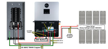
In your case off grid, I would disable bonding in the inverter, install a grounding electrode at the main breaker panel fed directly by the inverter and bond N-G there. I would remove the ground electrode at the panels and run a EGC from panel frames back to system N-G bond.

The reason for N-G bond at the main panel is if a generator is used that does not bond N-G, you have a bond in place. You could leave the current bond in the inverter in place instead of bonding at the main breaker panel. I would remove the ground electrode at the panels and install one at the inverter/main panel. If you do use a generator that is not bonded, you will have to use a bonding plug or jumper N to G in the panel.
 
Little off subject matter but on topic... Have totally off grid setup - never getting grid power either. Have 1 EG4 6000XP unit that's wired to a main breaker - not bonded. If using the internal bonding setting enabled, do I need earth ground for the inverter? Assume that is the case. Also, have solar panels earth grounded. Can I use the ground from the panels to ground the EG4 6000XP? The more I read about this the more it seems arcane! A little clarification would be super as most information on solar seems to forget about the folks that are completely new to this all.

An earth ground would be recommended. I would definitely check out the thread that ZWY sent as it has helpful diagrams for this.
 
Read through Filter Guy's paper... Still a bit confused here as it relates to the EG4 6000XP.

I contacted EG4 directly and they replied: "the inverter housing itself doesn't need to be grounded, but there is a ground bus bar in the cabinet labeled PE. That's going to be for your A/C inputs/Output like your GEN/GRID/LOAD Input/Output locations. Each one of those connections made will need four wires L1, L2, a Neutral, and a Ground." And that, "if you do not ground the inverter, that the ground should be made at your load panel, and then connected to the ground bus in your inverter."

This being said, let's say that the main breaker panel is earth grounded (then ground to inverter from panel) what should the setting for the EG4 6000XP internal bonding be - Enabled or disabled? My thought - it should be enabled and the panel not bond at N-G.
 
Last edited:
Read through Filter Guy's paper... Still a bit confused here as it relates to the EG4 6000XP.

I contacted EG4 directly and they replied: "the inverter housing itself doesn't need to be grounded, but there is a ground bus bar in the cabinet labeled PE. That's going to be for your A/C inputs/Output like your GEN/GRID/LOAD Input/Output locations. Each one of those connections made will need four wires L1, L2, a Neutral, and a Ground." And that, "if you do not ground the inverter, that the ground should be made at your load panel, and then connected to the ground bus in your inverter."

This being said, let's say that the main breaker panel is earth grounded (then ground to inverter from panel) what should the setting for the EG4 6000XP internal bonding be - Enabled or disabled?

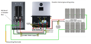
If you have a neutral-ground bond in the main panel, you would want it disabled. However, if not, you would want it enabled.
 
If you have a neutral-ground bond in the main panel, you would want it disabled. However, if not, you would want it enabled.
Ok. Which is the preferred method? Let's assume in future that a generator is added (non N-G bond) would it matter where the bond takes place?


EG4 6000XP - Wiring Diagram.jpg
 
Last edited:
Agree bonding should be in breaker panel not internally. EG4 6000XP default setting internal bonding is enabled, thus need to change setting 26 to disabled.

Note that the grounding on the frames of the panels will depend on the mounting system.
Panels are ground from unistrut to unistrut then to breaker. Assume that's fine? Or best to go panel to panel as you illustrated? Also, we installed a grounding rod at the solar panel location - needed?

The panels are built on wood adjustable mounts exactly like this:
 
Last edited:
Panels are ground from unistrut to unistrut then to breaker. Assume that's fine? Or best to go panel to panel as you illustrated?
The anodization and aluminum oxide are both insulators so the set-up with the washers holding the panels down may not have good electrical contact with the frames. If the grounding is to be to code there should be a commercial grounding lug bolted to each panel and a single wire going from lug to lug.
Also, we installed a grounding rod at the solar panel location - needed?
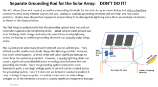
Actually, that is allowed, but not recommended. I would even say it is discouraged.

The grounding wire that connects the strut and panels together should be run back to the same grounding system of the house.

When there are two ground rods it can actually cause problems rather than solve problems.

1710545424291.png


You may want to review this resource:
 
Read through Filter Guy's paper... Still a bit confused here as it relates to the EG4 6000XP.

I contacted EG4 directly and they replied: "the inverter housing itself doesn't need to be grounded, but there is a ground bus bar in the cabinet labeled PE. That's going to be for your A/C inputs/Output like your GEN/GRID/LOAD Input/Output locations. Each one of those connections made will need four wires L1, L2, a Neutral, and a Ground." And that, "if you do not ground the inverter, that the ground should be made at your load panel, and then connected to the ground bus in your inverter."

This being said, let's say that the main breaker panel is earth grounded (then ground to inverter from panel)
Earth grounded is not N-G bonded, so some clarification is needed.

Ground electrode driven at main panel and bond N-G at that panel is what is referred to when N-G bonding in a stationary application. If a rod is driven into earth at that panel without any connection between N and G, then the panel is just earthed and not bonded.

what should the setting for the EG4 6000XP internal bonding be - Enabled or disabled? My thought - it should be enabled and the panel not bond at N-G.
Disable internal bonding. You have the ground electrode at the main panel, this is where you should also bond N-G.

Internal N-G bond in this inverter is for a mobile application that would never be plugged into shore power and would not have a ground electrode.
 
Agree bonding should be in breaker panel not internally. EG4 6000XP default setting internal bonding is enabled, thus need to change setting 26 to disabled.


Panels are ground from unistrut to unistrut then to breaker. Assume that's fine? Or best to go panel to panel as you illustrated? Also, we installed a grounding rod at the solar panel location - needed?

The panels are built on wood adjustable mounts exactly like this:
The panel clamps you are using are not rated for bonding purposes. You would need to use clamps that have a point that dig into the frame thru the anodizing.

My clamps do have that point but I also added lugs and wire as shown in this part of my video.
 
The anodization and aluminum oxide are both insulators so the set-up with the washers holding the panels down may not have good electrical contact with the frames. If the grounding is to be to code there should be a commercial grounding lug bolted to each panel and a single wire going from lug to lug.

Actually, that is allowed, but not recommended. I would even say it is discouraged.

The grounding wire that connects the strut and panels together should be run back to the same grounding system of the house.
Fair enough.. Makes sense to not have grounding rod at solar panels and run ground wire to the main breaker. Assume I run bare copper panel to panel then run THWN-2 (going into conduit underground) to main breaker. Recommended copper wire size for panel to panel grounding?
 
Fair enough.. Makes sense to not have grounding rod at solar panels and run ground wire to the main breaker. Assume I run bare copper panel to panel then run THWN-2 (going into conduit underground) to main breaker. Recommended copper wire size for panel to panel grounding?
6AWG is required. I used these lugs screwed to frames using stainless screws. The lug prevents the corrosion between copper wire and aluminum frame. UL stamped too. https://www.amazon.com/gp/product/B07G392449/ref=ppx_yo_dt_b_search_asin_title?ie=UTF8&psc=1&qty=3
 
1710613630460.png
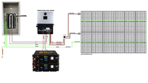
Here is what I put together from everything mentioned... Sorry for the blurry image, unable to upload the original as it's "too large"

NOTE: Only change I made was for the L1 & L2 which is 8/3 wire not 10/3.
 
Last edited:

diy solar

diy solar
Back
Top