diy solar

diy solar

New no battery pure sine wave solar power system with smart switchers.

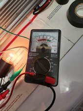
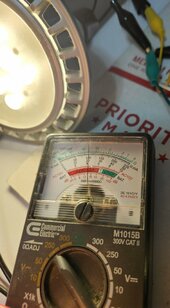
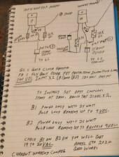
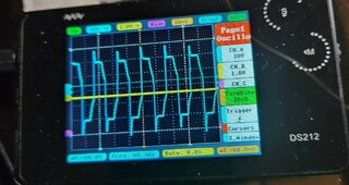
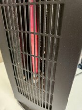
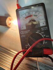
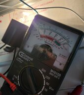
Wow both B1 & B2 at 140VDC 7 panels each with the FET gates running on a low setting 60Hz timing, Output from the inverter is at 220VAC. I have a stable situation running light bulb on a serious overcast day. For those looking for 220Volt 50Hz or 60Hz power here is your exit ramp.💚

My plan is to reduce the input voltage on both B1 & B2 till 120VAC output is achieved, after that hopefully full sun and full testing ahead.

Will back fill with solar panels for more amps once the input voltage mystery is solved.

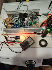
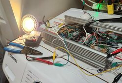
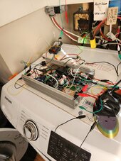
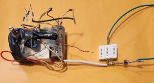
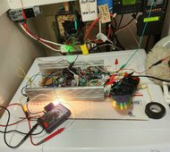
Have a nice setup for continuing to test the two FET inverter during day time hours just a matter of time till I dial in the right settings, it was a small setback when the 40N65 MOSFET shorted but it was also a big tell about what is going on inside that inverter once I adjust the drive correctly the energy that caused the shorted FET will come out of the inverters output as 120VAC goodness.
Just a short time till I get it.

Has been running for hours now in the 220Volt mode, minimal loads, target 120VAC before I start load testing, hope you understand.

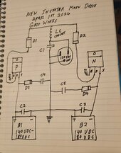
Current calculations suggest 4 panels each B1 & B2 for 85 volts 800 watts that still may be a notch high but the inverter will have the advantage 170 volt DC total input.

Something unexpected looking at 80 VDC or less main input voltage X 2 going forward instead of 180VDC, things like that make me happy 😊

The original circuit diagrams for the solar panels layout has to be wrong way too many panels, I will supply correct information later.
Best wishes
 

Attachments

  • 20240404_133317~2.jpg
    20240404_133317~2.jpg
    242.8 KB · Views: 2
  • 20240404_133307~2.jpg
    20240404_133307~2.jpg
    115.4 KB · Views: 2
Last edited:
Shutdown on the new inverter for the night with 50 watt load running for hours the FETs heat sink was cold to the touch.

Disconnected the solar panel inputs watched bulb dim out to zero and unplugged to 60Hz signal for a safe shutdown.

Tomorrow disconnect three panels each from B1 & B2 and retest everything again, looking forward to full sun now that we are looking at lower input voltage.

Another few steps forward today, increasing stability, and a hint that a optic coupler settings lower than what it takes to glow the bulb in the 21VDC test may be the perfect inverter setting at full voltage.

More soon
 
Last edited:
Good morning, B1 & B2 power power sources are at solar 80VDC, heavy overcast sky waiting for full sun, currently the new two FET inverter is running smooth with a 25 watt bulb load and 115VAC 60Hz output. Here is your exit ramp for 120VAC 60Hz or 50Hz power production with the new two FET inverter.❤️

Initial perfect performance, B1 with 4 standard 12VDC solar panels and B2 the same 800watts if you (4+4) on each input keeping the same 80VDC you can get 1,600 watts approximately.

Load testing will progress slowly today💚

First load test added 30 watt soldering iron to 25 watt light bulb, Mixed results unacceptable voltage drop to 98VAC but the lamp and soldering iron working just fine, suggesting higher optic drive output adjustment is needed. This will be a slow process to increase the inverter output amps but I am up to the challenge.😀
More information soon
 

Attachments

  • 20240405_104027.jpg
    20240405_104027.jpg
    145.3 KB · Views: 2
  • 20240405_104049.jpg
    20240405_104049.jpg
    181.6 KB · Views: 2
Last edited:
As it stands right now the inverter can run 6 of the 9 watt LED bulbs 60watt equivalent, during this test I disconnect all loads except the voltage meter the voltage spiked and the N channel FET went shorted source to drain.

Although the N channel failed shorted once I disconnected the input power source for the N channel the active P channel relit the bulbs, P channel FET servives everything every time.❤️

P channel FET is the largest physical size I have ever owned and seems immune to abuse, Need to aquire a N channel FET that is its equal in every way for the big win!

Several changes are needed here, more later. Two steps forward and one step back.

Taking a moment to mark the progress here took a fantasy drawing of a two MOSFET inverter and as of today we are starting to run things long-term lights/ heat, many more adjustments needed
to get full power.
 
Last edited:
Getting ready to install the third good used 40N65 MOSFET on the two FET inverter to restore operation, not sure the direction to take next to increase amperage but small steps will show the correct way/direction.

Was seconds away from showing you multiple LED bulbs burning brightly when the N channel went down.

More soon
 
Inverter restored, as an experiment going to test the lowest possible inputs on the optic couplers, seriously don't think this is the direction needed but new project needs the data, will also test the setting slightly higher than the previous testing looking for a boost.

Bench testing and preparation for tomorrow, unexpected voltage surges need to be solved.

More soon
 
Good morning up early, I will post today's updates on this post check back several times. First thing in past testing when the optic drivers were tuned much higher I was getting alot more than 55 watts of energy. It is going to come down to one of three things.

1. Need much lower optic coupler settings and higher voltage from the solar panels B1 & B2, prepared to test this currently at 80VDC and can go up 20VDC at a time to 180VDC.

2. Need a higher optic coupler output settings than previous test but less than full. Prepared to test as well.

3. Not driving the gate FETs correctly, With the correct FETs, driver and DC input voltage with baby step testing I should find the the output these Mosfets are rated for.

Proceeding slowly have discovered a long range of optic coupler settings well below what it takes to glow the bulb in the 21VDC bench testing, may have discovered the voltage control I have been looking for if this is the correct path soon will be uping the voltage from the solar panels.

Have finally found voltage control for the two FET inverter AC output! This will pay off big time in the long term have lowered output voltage from 115VAC to 60VAC, Unfortunately will need to reconnect the panels I disconnected a few days ago to get it back up to 120VAC.

Great news just passed 225 watt load test and the inverter is still running, 115volts AC output 60Hz with solar input 140VDC for B1 & B2, output voltage much more steady. Pushed small Honeywell space heater and LED spot light working smoothly.💚

Secret is a very low optic coupler setting and higher input solar panel voltage got it right the first time for 120VAC 140VDC input, 220Volt will require more panels, have improved operations by small increase in LED brightness on both channels, hope to nail it all down soon with diagrams and correct parts list.

100K potentiometers on the optic couplers work perfectly once you look for and voltage test the FET output voltage you get perfect control, Works great but needs more fine tuning, was going to double check the flyback diodes on the FETs to see if they were causing any issues but as of right now it is full steam ahead 😀

Taking a break now.
😀
 

Attachments

  • 20240406_123048~2.jpg
    20240406_123048~2.jpg
    99.3 KB · Views: 6
  • 20240406_123037~2.jpg
    20240406_123037~2.jpg
    326.6 KB · Views: 1
Last edited:
Big success today, check previous post.

For tomorrow going to beef up all main DC inputs and try again, was making live adjustments on the inverter and found a sweet spot just before ending testing for the day, could really use a second 100K potentiometer.

Winning this 💚
 
Last edited:
Detail diagram of what I have working with the FET numbers with part values and optocouple setup instructions.

Small changes expected as we go forward, more testing tomorrow.

Current look at the stereo output , The upper and lower spikes are from the 50% duty cycle voltage spikes, still working on capturing and turning it into more energy. Just need to level it off or sloped slightly.

More soon
 

Attachments

  • 20240406_192747~2.jpg
    20240406_192747~2.jpg
    157.3 KB · Views: 8
  • 20240406_181149~2.jpg
    20240406_181149~2.jpg
    287.5 KB · Views: 2
Last edited:
520 watts continuous output from the new two FET inverter running space heater on first stage and light bulb. 100 volts 60Hz fan motor runs smoothly heater is providing good output.

Success ❤️

Running great considering it is all on alligator clip jumpers.

Sure to make more improvements, solved many mysteries in the past few days concerning driving the FETs. Loving it!

Ventilator fan for the two FET inverter heat sink is now 24/7 powered, soldered and insulated many inverter connections.

Nice way to start a day, more later 😀
 

Attachments

  • 20240407_091610.jpg
    20240407_091610.jpg
    152 KB · Views: 7
  • 20240407_091553.jpg
    20240407_091553.jpg
    175.2 KB · Views: 8
Last edited:
B1 seven solar panels 140VDC.
B2 seven solar panels 140VDC.
60Hz signal derived from two small grid powered transformers work on the 555timer will continue soon.

Low load on the inverter 125VAC, warning right now no load causes issues with the stability of the inverter, another thing to work on.
Recommendation use 25 watt standard bulb minimum till I fix this. Not tested yet but inverter direct connection to an ISO transformer may automatically cure several current issues no load, spikes in sinewave, rounding the sine wave, and most important of all when this thing has a FET fail fault it channels DC voltage directly to the output only way to properly protect you and your equipment is to use an isolation transformer (ISO)⚠️
DC can not pass through a AC transformer especially an ISO transformer.

Best wishes 💚
 
Last edited:
First bad news new inverter pushes wound AC motors OK but brush motors like a vacuum cleaner or saws all is a big No.

Shorted out both FETs, Yes I finally killed the P channel FET, fortunately I have backups, also going to order more FETs now that I have a clue what I need.

Don't like killing parts but also need to know this stuff to make forward progress.

More later.
 
Ordered more (5) 40N65 MOSFETs N channel and a different part # P channel Mosfet rated for 200Volts 11amps getting ten of them.

Since I just stole the P channel FET from the test card board based inverter it will be rebuilt with cheaper parts it will be eventually tested with earth ground and is not expected to survive.

I see nothing but good to coming from the past three days of testing the new two FET inverter.

More soon 😀
 
Double FET replacement and the inverter is back 100% operational.

Exact Mosfets as before, Both P and N channel FETs were shorted source to drain, how it did not blow a 5amp fast blow glass fuse on either side whilst it cooked a 20amp N channel FET and 40amp P channel Mosfet blows my mind.

If it wasn't amps it must have been a voltage spike in excess of 500 volts!

Best wishes More tomorrow
 
Last edited:
Had a brain storm, hope it works, based on today's testing the lower the optic couplers and the higher B1 & B2 voltage the more amps output you get.(Over 500 watts currently)

Instead of 140VDC for B1 & B2 if I raise the input voltage back to the original 180VDC and tune the optic couplers back down to 120VAC output guess what's going to happen with the output amperage?

Bet it increases, all that energy that has been killing the FET parts will go to the output.

Tomorrow promises to be exciting, Success with this will put the Project system and the new 2 FET inverter on the same platform 😀
 
Last edited:
Starting today with a new optic coupler settings, on a 21VDC bench test.
5VDC on B1 inverter output only.
-5VDC on B2 inverter output only.
Check: B1 on B2 on inverter output is 9 to 10 VAC. Standard 25watt 120VAC bulb for load.

Both B1 and B2 solar panel arrays will be put back to the original 180VDC configuration.

Wish me luck, Slow testing ahead, Hope to have a working two FET inverter at the end of this day.

More soon 😀
 
Last edited:
Starting today with a new optic coupler settings, on a 21VDC bench test.
5VDC on B1 inverter output only.
-5VDC on B2 inverter output only.
Check: B1 on B2 on inverter output is 9 to 10 VAC.

Both B1 and B2 solar panel arrays will be put back to the original 180VDC configuration.

Wish me luck, Slow testing ahead, Hope to have a working two FET inverter at the end of this day.

More soon 😀
Be careful when you get on the roof to reconnect those panels!
 
Be careful when you get on the roof to reconnect those panels!
Down from the roof due to rain, my B2 is back to 180VDC, B1 is not working and I opened several connections till I can figure out why the problem exists.

Two FET inverter adjusted and ready for testing, just have to fix B1 DC supply, game called due to rain.

Have a chance to put the third set of 9 panels180VDC on its own set of conductors for the new systems.

More soon
 
Last edited:
Both B1 & B2 are at 180VDC, Two FET inverter output 120VAC 60Hz.💚

Have full control ❤️ but 100K potentiometer adjustment is touchy.
Bet a 50K potentiometer would work better operating near one end.

It is working but raining outside so I am going to wait for more sun to load test the inverter, everything looks good right now.

Think I can now connect the input diodes for more energy. Feels nice to actually have adjustable voltage control.

Both the new two FET inverter and the Project system share the same 9 standard 12VDC solar panels 180VDC input. All I have to do is connect one solar input wire together and I am ready for summer and testing the heck out of this inverter.


It really works 😍
 

Attachments

  • 20240408_125614.jpg
    20240408_125614.jpg
    119.7 KB · Views: 2
Last edited:
Just figured out passing the full inverter input through a pair of diodes to collect the voltage spikes is a bad approach, instantly putting the direct inputs back the way they were, any spike modifications will have to be done down stream of the main.

Still making progress on all fronts just a short time till I lock in on the best configuration for power production.

Going to call it a day, raining outside
 
Last edited:
Came up with a idea to filter/change the spikes while not interfering with the main power flow. Picture

Just a little more testing, already had it running smoothly enough at 140VDC to convince me. Just need to move the two diodes I currently have to make this work.

This is going to be great!

More soon
 

Attachments

  • 20240408_195828~2.jpg
    20240408_195828~2.jpg
    127.7 KB · Views: 7
Last edited:
Today it is expected to rain all day, Going to work on other things till the sun shine returns, once I get the inverter running again at more than 500 watts it will be tested with the 10amp ISO output transformer, I have a feeling that many of the current stability issues will dissappear once the inverter output is run through the transformer.

Working to bring the third set of 9 panels 180 volts DC down on it's own wire to the inverters.

I have been warned to stay on subject but my EV car solar charging is a big part of this unique power project, Car has been at the dealership since before Thanksgiving waiting for a new main high voltage battery related to a national recall on about 2,000 cars, Was told late December the battery was on US soil and under going customs inspection.

About two weeks ago I was informed by the dealership the battery is back ordered with no additional information,
They are only offering $4,000-$5,000 in trade on a car that is waiting for a $20,000 battery plus I paid $24K for a car that only delivered 20,000 miles before it died on the side of the road, paying full insurance on the car, Just renewed the EV tag for another year $235, paid over $200 to have the car towed to the dealership, this is my wife's main car with no loaner because I didn't purchase the car at the place the repair is to take place, No one is doing anything to help us, Any advice?

If I knew then what I know now, My advice Don't buy an electric car.


More soon 😀
 
Last edited:
Always more going on behind the scenes than you can imagine, just put the two 180VDC feeds back on the Project power system and took it out of night mode where it has been for the past several days of operation.

Next is to hard wire the third 180VDC feed to the inverters in preparation for running the mini split air conditioner in summer,

I like being able to individually test each solar array if necessary, all three glass fused at 5amps.

Have not lost any solar panels due to using direct drive input but have one example of a blown 5 amp glass fuse off a 9 panel array.

More soon 😀
 
Last edited:
Expecting a few more days of rainy conditions so I will build another 12VDC floating power supply and attempt to move the 555timer 60Hz signal to on board inside the inverter.

Since the timer will be powered by the outside + & - feeds it will properly trigger both P and N FETs, I now know exactly what to look for in triggering the Mosfets. No additional transistor circuit to correct logic will be needed.
Also the better square wave of the 555 timer will push more energy/amps.

Best news is I will get my step down transformer back so the oscilloscope can analyze the full power sine wave.

More soon

Picture 555timer ready with 5VDC power supply for final bench testing and installation into two FET inverter.
 

Attachments

  • 20240410_143430~2.jpg
    20240410_143430~2.jpg
    270.5 KB · Views: 1
Last edited:

diy solar

diy solar
Back
Top