diy solar

diy solar

Luyuan battery case

Amy went above and beyond to ensure the cells arrived safe.
Agreed. Her packaging methods are exceptional. When I received my first batch of CATL cells a number of years ago from a different vendor all went well except one box. In an effort to save money they put the bus bars in a box and included it in one of the battery boxes. Right over a cell terminal. Well you guessed it. That corner of the box was crushed and it bent the terminal of the battery causing a leak.

Amy organizes her packing to avoid such things. If one orders cases the hardware is usually placed in one of them or a separate box. There was one box that mixed the two but it was organized in such a way that both the battery and terminals were protected.
 
My 280k 8s is fully assembled and trickle charging with the bench top PS just to see how she does.

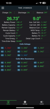
Been feeding it 270w for the past hour or two, love the cell delta. After taking care of the rust in the case, nothing exciting for the rest of the build, very routine in the 8s JK. The dual threaded hole and flexible bus bars are very confidence inspiring, soon as the spring washer is compressed, torque just climbs for 1/8 turn till she’s done at 50in lbs.

I’ll prob just toss a couple more AH into it then check the torque on cell connections then secure the case top screws and she heads up to camp next weekend to meet her 230ah friend.

The small PV system (340w) to take care of the rest of cell balancing if any is needed.

Next up is the 4 other cells I picked up for a 12v battery to build to put my JBD 4s BMS to good use, no rush on that, still deciding on a case and bits and parts.
 

Attachments

  • IMG_3884.png
    IMG_3884.png
    224.1 KB · Views: 4
  • Like
Reactions: Zwy
I'm not sure if I'm going to use the included flexible busbars or not. I don't need the flexible part. If the flexible busbars have more resistance than a solid busbar I won't use them.
 
Just remember to Calibrate the BMS !
Do so by NOT connecting the pack to anything else. (Breaker, Charge & Discharge ON)
1) Assemble the pack and setup the BMS as you need to.
2) using a 2 or 3 Decimal Accurate DMM/DVOM measure the voltage on the Battery Pack Terminals with 0 AMPS going in/out (that is for correction if connected)
3) Enter that value from the terminals into the config page.

TIP: I use my YR1035 Cell Tester as it is accurate by 3 decimals and can handle up to 100VDC. Even my old YR1030 does this perfectly.
TIP2: Configuring your BMS advanced settings, start at the BOTTOM of the setting and work up. That takes care of dependent values being set in sequence, preventing the "settings out of range" etc errors. (JK Inverter Model)
 
Yeah all settings have been updated, who wants low temp cut off set for -10c, and balance to start at 3.40v?

As for calibrate, I don’t have my decent meter on me (left it up at camp), just an el cheap manual scale unit and anything above 20v needs to jump to 200v scale and it drops to 10ths for max resolution.

I may just do cell voltages, and add them up or times 8 as close enough.
 
My cheapo DVM has more decimal digits than my Fluke 325. I did check the accuracy of all my volt meters using the Voltage Reference device from VoltageStandard.

I'll see what my YR1035+ says. Need to check that against the Voltage Reference device. Forgot to do that.
 
The 1035 is MORE Accurate but the BMS only accepts 2 decimal places, not 3 so it's perfect. I have all my current online packs in synch and the 3 next ones (going in tomorrow) are already set to "join the family".

BTW, I start Active Balancing at 3.420 - float is at 3.470 and bulk/absorb is 3.5. In <15 minutes of hitting float, all at 0.006 variance. It is SEXY & Lovely !!! (shhh don't tell missus)
 
My bulk is 3.425 and absorb is at 3.40 for 2 hrs, seeing this is a weekend warrior setup she’ll typically sees a lot of absorb time.

We did back to back weekends, and this past weekend, we arrived at 62% (due to weather during the week) and left at 52% SOC. I shut off the inverter (sorry no night lights mice). The inverter uses 440whr, each day the little array was getting 220whr to 800whr. This time I’m sure she’ll be at 100% when we’re back next week.
 
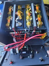
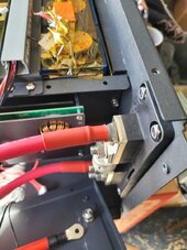
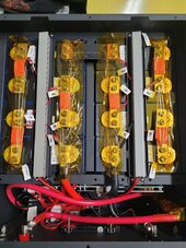
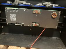
My cases all went together awesome. I did instal the class T fuse on inside of the case. I countersunk holes for flathead screws. My local Ace hardware even had black M6 screws. To me, it looks clean and no brackets were needed.
I had to use 90° lugs on the fuse holder to make it fit nice.
The kapton tape is on the fuse because the dealer gave me the large fuse holder (<225A) for my 200A fuses. So I had to grind out the fuses to make them fit. I know, that's not recomended but we had to leave on our road trip and I will have them swapped out when I get back so I didn't want to modify the covers. The good news is that the smaller Blue Seas fuse holder has the exact same mounting hole size and pattern!
I also switched out the balancing lead terminals with Ancor heat shrink terminals. They just seamed beefier and more secure.
Other than the wrong fuse holders, I am pretty happy how it all came out.
Thanks to all of you for your help and giving me the confidence to do this! All your discussion, pictures, and video (@Zwy) really made a difference! Especially to @Steve_S for making it so easy to have Amy give me exactly what I wanted. I literally just said I want the batteries that Steve ordered but with 304A cells.
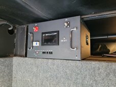
Plus two of the batteries fit on the shelf of my RV basement with about 1/4" of height to spare!1000003170.jpg
20240715_164423.jpg
20240715_081710.jpg
20240713_083009.jpg
 
Last edited:
Top balancing has commenced. It was delayed due to an OCD technician that didn't like how the provided flexible busbars stacked. A couple millimeters of the heat shrink on the flexible part of the busbar (where it meets the non-flexible part) was trimmed back to ensure that the stacked busbars were making proper contact. That took much longer than I expected even though I trimmed only half the busbars.

I'm top balancing 9 cells at a time. Not enough of the provided busbars to do any more than that.

DIY Tip: Use two screws in each terminal. Avoid the temptation to use just one. With my YR1035+ I checked the resistance from the extreme ends and found that once I put the second screw in each terminal, the resistance dropped. Maybe not a huge amount, but enough that the meter could tell the difference.
 
My cases all went together awesome. I did instal the class T fuse on inside of the case. I countersunk holes for flathead screws. My local Ace hardware even had black M6 screws. To me, it looks clean and no brackets were needed.
I had to use 90° lugs on the fuse holder to make it fit nice.
The kapton tape is on the fuse because the dealer gave me the large fuse holder (<225A) for my 200A fuses. So I had to grind out the fuses to make them fit. I know, that's not recomended but we had to leave on our road trip and I will have them swapped out when I get back so I didn't want to modify the covers. The good news is that the smaller Blue Seas fuse holder has the exact same mounting hole size and pattern!
I also switched out the balancing lead terminals with Ancor eat shrink terminals. They just seamed beefier and more secure.
Other than the wrong fuse holders I am pretty happy how it all came out.
Thanks to all of you for your help and giving me the confidence to do this. All your discussion, pictures, and video (@Zwy) really made a difference! Especially to @Steve_S for making it so easy to have Amy give exactly what I wanted. I literally just said I want the batteries that Steve ordered but with 304A cells.
Plus two of the batteries fit on the shelf of my RV basement with about 1/4" of height to spare!View attachment 229764
View attachment 229784
View attachment 229789
View attachment 229795
I think the 304 cells have the same dimensions as the 280k at least that’s what Amy said as far as what they make for cases

Was your large bus bar (cell 4 to 5) bare copper or tin plated? Also you add the heat shrink to it?
 
Was your large bus bar (cell 4 to 5) bare copper or tin plated? Also you add the heat shrink to it?

It does look like bare copper, doesn't it? Mine is tin plated with no heat shrink.

Since I had to trim off some of the heat shrink from the busbars, I think the heat shrink does not have adhesive.
 
Yeah, compared to the other bus bars, def looks bare copper.

Crazy the parts are all random for these kits.
 
I think the 304 cells have the same dimensions as the 280k at least that’s what Amy said as far as what they make for cases

Was your large bus bar (cell 4 to 5) bare copper or tin plated? Also you add the heat shrink to it?
I believe the 304A are just a hair larger than the 280A but not enough that everything still fit really nice.

The cell 4 to 5 busbar is bare copper and came with the heat shrink. I just followed what @Zwy did in his video: give them a little sanding with some 220 grit, then wiped them with alcohol, and applied a thin coat of Noalox. I also did this to the little copper bars on the BMS terminals that Amy sent.
 
Also odd mini BMS bus bars are included on the JK inverter BMS, yet none provided on the standard 8s 200a JK.
 
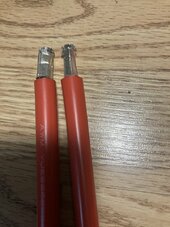
Ok. It was suggested to use a 20 mm crimp die and recrimp with 16mm. Alas I only had 25 and it was too loose.

I did a combination 25mm - 16mm crimp and then rotated 90 degrees and recrimped with 16mm.

IMG_4358.jpeg
 
For some reason it was easier for me to put the bottom attachment screws in first. Made it easier for me to line things up. Might be different for another person.

IMG_4360.jpeg
 
Ok. It was suggested to use a 20 mm crimp die and recrimp with 16mm. Alas I only had 25 and it was too loose.

I did a combination 25mm - 16mm crimp and then rotated 90 degrees and recrimped with 16mm.

View attachment 229926
I did the same thing with the original thicker copper ferrules, then I tried again with the thinner flared tinned copper ferrules (the ones you showed) but after seriously "tightening" them into the breaker realized there is no point in crimping them first because how the breaker actually crimps & bites into the ferrule. I pushed high amps through to see if anything would be different and NOPE nice & cool at 200A sustained.
 
I did the same thing with the original thicker copper ferrules, then I tried again with the thinner flared tinned copper ferrules (the ones you showed) but after seriously "tightening" them into the breaker realized there is no point in crimping them first because how the breaker actually crimps & bites into the ferrule. I pushed high amps through to see if anything would be different and NOPE nice & cool at 200A sustained.

I was wondering if the expectation was that the breaker terminal was expected to "crimp" the ferrule. The other option was that they ferrule was placed there just to protect the wires until it was installed.
 
I am no expert but it seems that thin ferrules are more to contain the strands while the clamp on the breaker is tightened and you want it to form to the clamp. The thicker ferrules are to be crimped via a crimper before insertion in a clamp.

Which makes me think I could have simply bought cheap thin ferrules for my original class T blocks instead of buying new lug-based fuse blocks, but whatever.
 
I was wondering if the expectation was that the breaker terminal was expected to "crimp" the ferrule. The other option was that they ferrule was placed there just to protect the wires until it was installed.
The ferrules need to be there. The silicone jacketed wire as you noticed has ultra-fine strands and need to be "managed" and kept together & tidy with no loosey goosey's laying about.

Actually, unlike Midnites Polarized DC Breakers which have no tooth or grippers, the Breakers from AMY have "teeth" to grab everything pretty well. I did cut one wire with ferrule after it was heavily crimped into the breaker and the strands were really squished together & tight. I also ran 200A through one setup and no warmth or heat.
 
Please learn from my near expensive mistake. No excuses, already had the 2 cups of coffee.

When wiring the BMS leads make sure you are following the diagram provided earlier. It is excellent. I made the near expensive mistake of reversing the orientation placing the temperature sensors on the wrong side. I normally run a multimeter check on the lead harness before plugging it in. The numbers for the right leads were negative. The readings on the right side were equally "interesting".

I placed the temperature sensors on the proper side and rewired my terminals. A multimeter run (twice to make sure) showed the proper values.
Ouch !!! Hoping you ddn't cook the temp sensors by doing so... (should not have, especially if not connected to BMS.).

PEOPLE ALSO NEVER FORGET Static Electricity can FRY your BMS use proper precautions before handling, ground yourself before touching stuff so you don't zap it. I CRINGE everytime I watch a vid or something and a derwood tosses the BMS around without a care not realizing they could have cooked it.... Funny party, 1 Well Known YT Character did just that not realizing it and chased the "fried - defective from factory (not) BMS" and was upset the company was hesitant to replace a derwood caused issue.
 

diy solar

diy solar
Back
Top