diy solar

diy solar

House burned down

The take away on Solar power is that the installation is a system with many interdependent parts, all of which must be designed to fit together properly and safely - called a reliability chain. One weak link can make the whole system crash.
 
I would need to heat the batteries and inverter in the winter. It can get to -10F here in Wisconsin. And at the same time that I would need to heat the insulated shed, I would be netting about 8-12kW / day making it completely pointless. All of my solar would go to heating the outbuilding and it probably wouldnt be enough.
Do peeps puts power wall battery banks down in their basements. In the frozen north, dont they have heated garages? Maybe you would need a sump with a steel lid to put the whole battery bank. At least the fire Dept could fill it with water. All electrical switchgear, inverters inside a steel cabinet. All important cable cutters, gloves and goggle permanently hooked on the wall.

Hmm, a fire resistant tank that can be flooded - and a high mounted water reservoir tank. Silica blanket - got some of this, cheap and really effective. Whats not to like?

Last resort, buckets of sand
 

Attachments

  • image_2024-07-27_044217609.png
    image_2024-07-27_044217609.png
    107.1 KB · Views: 4
To add to this, that outbuilding should also be air conditioned to keep the batteries and electronics cooled.
sure take all possible and reasonable precautions. though I think if you double walled the structure with insulation between both walls and an air space separating the two your need for a/c would drop dramatically except for in the desert locations.
 
I would need to heat the batteries and inverter in the winter. It can get to -10F here in Wisconsin. And at the same time that I would need to heat the insulated shed, I would be netting about 8-12kW / day making it completely pointless. All of my solar would go to heating the outbuilding and it probably wouldnt be enough.
close to the same temps in the winter, -5f for me. I heat my batteries and it does not use that much at all, I do not heat the entire structure though, just the batteries. XPS foam battery boxes aluminum spreader plates and the heating pads. no controls what so ever just wire the pads in series spread them across the plates and let ohms law control the output for you. batteries hang out between 15°c and 25°c. no controllers, no logic circuits, raspberry Pi's or ardurino... nothing to monitor other then a temp data logger (which I no longer look at.) I have photos of the battery banks spaced across this forum specifically in ones concerning cold weather use and offgrid use.
 
The fuse picture i posted was just an answer to the "what is a meltfuse" question.
The exact fuse was a mega 48v, 300 A.
Can it be, that the battery was 48V nominal too?
Such batteries go wide over 48V, up to 58V regularly when charging and possibly, even much more for a few ms when the fuse blows under full load.
That is more than enough to start a DC arc, which is specially hard to extiguish.
I think, the fuse should be rated 64V-DC. at least.
DC is weird.
 
That is more than enough to start a DC arc, which is specially hard to extiguish.
I think, the fuse should be rated 64V-DC. at least.
DC is weird.
I have a theory that a simple plant spritzer water spray is more than enough to extinguish an arc fire <48V. It takes the heat away and the arc stop ionising.

But I havent set up my test bench yet to prove it

Anyone else have a go - try using a dc arc stick welder and get OH to spritz the flame. The arc volts should be ca 20V (though it starts at 60V and Amps ca 100A
Be sure to dip your rod in wax first before testing, most hyperbaric welding is in the 300-400amp range maybe at the amperages were using the arc wouldn't sustain but I'd be inclined to think the water will just vaporise but wetting the surrounding area might prevent the arc from spreading.
 
I meant to extiguish the arc without human intervention.
DC breakers have magnets to push the arc into ceramic chambers.
Ceramic DC fuses are normally sand-filled to cool down the ionization.
Agreed this is supposed to be how it is fundamentally achieved. Where it goes wrong is with Big Corp rush towards market dominance (profit) by miniaturisation (in ac terms miniature circuit breakers aka MCBs) and trying to force the fundamentally different current handling into the same sized form factor as could be achieved with ac current.

dc MCBs have polarity, and if you get it wrong the flame goes in the opposite direction and can start a fire.

Vid shows the ubiquitous Moeller MCB that was a mandatory 2012 requirement by the OZ Gov for every solar installation - very big down under. The Gov overlooked the Joe Public factor who would likely get the polarity wrong (this product banned and hastily replace)

This vid lacks was presented by a leccy and lacks scientific rigour but you get the point clearly I hope
Note this vid was only at 12.5A dc

- roof fires waiting to happen.
 
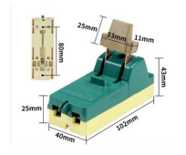
FWIW this is how dc currents were interrupted aka knife switch

and below is the post war version Siemens pattern (a 30A and a 63A albeit only rated for ac domestic use). This type is in common use by millions throughout the far east and is readily available on Alix <10$. I have some of these - seem very solidly made no Cheap charlie has got at it. I have as yet to test it on dc currents when I get my test bench set up. I believe these might well perform a creditable function <24Vdc on solar panel interruption. Yet to be demonstrated. But it shows that Big Corp knew all about the dangers but pursued profits instead.

IMHO no domestic system should every be run above 24Vdc. 48Vdc systems have a 10 fold higher risk of arc flash fires. But that makes me a heretic I suppose.
 

Attachments

  • Screenshot 2024-03-14 231918.png
    Screenshot 2024-03-14 231918.png
    109.5 KB · Views: 6
  • Screenshot 2024-03-14 231719.png
    Screenshot 2024-03-14 231719.png
    140.7 KB · Views: 6
FWIW this is how dc currents were interrupted aka knife switch

and below is the post war version Siemens pattern (a 30A and a 63A albeit only rated for ac domestic use). This type is in common use by millions throughout the far east and is readily available on Alix <10$. I have some of these - seem very solidly made no Cheap charlie has got at it. I have as yet to test it on dc currents when I get my test bench set up. I believe these might well perform a creditable function <24Vdc on solar panel interruption. Yet to be demonstrated. But it shows that Big Corp knew all about the dangers but pursued profits instead.

IMHO no domestic system should every be run above 24Vdc. 48Vdc systems have a 10 fold higher risk of arc flash fires. But that makes me a heretic I suppose.

AC vs DC 220V ,,, Some Differences 😁;

 
AC vs DC 220V ,,, Some Differences 😁;

Yes Ive seen that vid, but what the presenter doesnt mention is the current (I assume its a 1kW fire bar so a nominal 5A drawn (say 5000J) but the voltage applied is 220 V. You wouldnt get this effect at say 22Vdc because the initial arc heat is only 1 percent Joules. Notice the arc extinguishes quickly at ca 5mm separation. However if you increase the current 10X to 50A then you are back to 1000J and may expect a similar effect at 24v level . Must set up my bench. My own Lion fire has demotivated me somewhat.
 
Here's another of those Moeller polarised mcbs

OBTW, hadnt occurred to me but. mcbs come in pairs of poles (in/out +/-) You can wire these as a single pole breaker with the output of P1 looping to the input of P2 (effectively reversing current flow). So which ever way the current is flowing one of the poles will break the current.

Well thats the theory - anyone tested this ?

On one hand it seems mickey mouse but theoretically it should be sound? What do you think?

Personally give me a chunky knife switch any day.

This guy rabbits on about polarised breakers
but doesnt offer a solution - IMHO he chickened out - bit of a fraud.

Here's a TomZN non pole breaker tear down by our venerated BigClivedotcom

Scary - would you trust this at 48V 125A? Would it still work at lower disconnect levels, say 10,25 50A levels. The magnetising coil doesnt get the same force? Anyone know?
 
Last edited:
Should work, but you only get 1x voltage interrupting, not 2x.

For parallel PV strings, I suggest ganging breakers if polarized, to take advantage of that.
Overloaded one trips, correctly oriented ones interrupt the current.
In theory.
 
Each bank has its own fuse. The system had fuse all over the place, each inverter, each solar charger, each bank etc... but it is one of the fuses of one of the battery banks that blew. The inverters combined could never give more but 15 kw.
What the trigger of the event was, no idea. The expert could only locatie the source. Everything is destroyed.
I think from your description that is exactly the issue I have been grappling with on another thread. Ultimately it seems lifepo4 batteries required a fuse with a minimum of 20,000 amp interrupt rating, so that the arc cannot continue and the current is effectively cut before fire occurs. The only type of fuse I can find suitable is T type fuse with a DC AIC rating of 20,000A. All other types, Mega fuses, NH or FH fuses etc, are rated for AC interrupt and not DC Therefore your type of fuse was incapable of controlling the short that caused it to fail. Attached is a discussion paper that outlines the issues between AC and DC interrupt rating. It's complicated but worth the read. I am currently in the process of buying T fuses for each of my 280AH 12v batteries. Bloody expensive but I don't see any other option. Especially after seeing your pics and your story. Thank God you and family are alright.
 

Attachments

  • Fuse-Protection-of-DC-Systems.pdf
    164.1 KB · Views: 4
You have 2 conditions in usage. a) utility fuse to protect down stream wiring, b) main fuse to break current at incoming source in the event of a short circuit. You also have isolating switches which should not be used to disconnect live loads - they are for maintenance and safety. This simplistic view is the one held by those working with ac power.
With dc power we have to consider the case of arc flash where a sustained arc can be maintained - and cause a fire.

Several issues to consider

a) the gap obtained after disconnection, 5mm? or 50mm?
b) the current flowing - this affects the energy available to ionise a conducting path of copper vapour
c) the voltage applied - this will appear across the gap and support arc flash (fyi rule of thumb12V will not support a sustained arc, but 24V will over a distance of 50mm)
d) the ionised path is a negative resistance region and will rapidly enable flow of as much current as available from source
e) an arc needs continuous energy input to sustain a high temperature needed for ionisation

To quench an arc you can

a) remove energy source
b) remove heat - air blast, CO2, sand, powder gypsum, magnetic arc deflection to metal labyrinth, spray water mist - my contention tba
c) increase the gap
d) last resort - cut cable with professional cable cutter (not simple pliers)

Safety
When dealing with potential arc flash, always wear goggles (or get hit in the eyes with a jet a copper vapour)
Wear protective gloves. Dont wear flammable clothing - or anything soaked in fluid, like oil etc.
Always keep cable cutters on a hook nearby. Keep a bucket of dry sand. Kitchen tongs to handle hot objects.
When dealing with Lion batteries (should be outdoors), maintain a clear escape exit. If one kicks off - run away you may only have seconds. Dont charge Lion cells leaving unattended (phones, laptops etc)
 
I think from your description that is exactly the issue I have been grappling with on another thread. Ultimately it seems lifepo4 batteries required a fuse with a minimum of 20,000 amp interrupt rating, so that the arc cannot continue and the current is effectively cut before fire occurs. The only type of fuse I can find suitable is T type fuse with a DC AIC rating of 20,000A. All other types, Mega fuses, NH or FH fuses etc, are rated for AC interrupt and not DC Therefore your type of fuse was incapable of controlling the short that caused it to fail. Attached is a discussion paper that outlines the issues between AC and DC interrupt rating. It's complicated but worth the read. I am currently in the process of buying T fuses for each of my 280AH 12v batteries. Bloody expensive but I don't see any other option. Especially after seeing your pics and your story. Thank God you and family are alright.

Maybe;

IMG_1248.jpeg

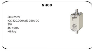
Cost 🤷‍♂️ ,,, Apparently $10 😳

More available in Europe, but maybe in NA 🤷‍♂️.

Here is a Good Video on Fuses that another Forum Member posted;

 
Last edited:
Where is the link to source? There are a lot of Cheap Charlie fuses around. One member posted that one type was all the same inside whether 10 A or 100 A, just a different label.. Most of us are not set up to test these other than whacking them across a car battery with headlamp bulbs in series? When you need them so you dont toast your wiring harness - then you find out they are fake.

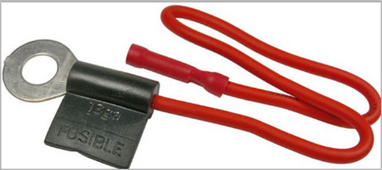
Btw here is a GM auto fusible link to protect a dynamo. Original fitted in 1930's + cars trucks. IMHO you can make the same with a piece of fuse wire 2 or more gauges below load wire (say 18awg vs 12awg) ca 9" long put inside some silicone rubber tube. Magic eh , nothing up my sleeve. The SAE has a standard on this

Fusible Links(STABILIZED Jul 2022) J156_202207, Not so mickey mouse eh?​


image_2024-08-04_174349669.png
 
So I am new to this group, couple questions

people keep mentioning that you need for 20k AIC for LIFEp04. Where are people getting this amp rating from, I have seen no links or white papers showing this kind of amperage from normal cells, Most of my reading indicates normal cells in 12/24/48 series configurations are only capable of around 1000A dead short. Parallel strings would all have independent fuses. Most rack enclosures packs, are using a 6k to 10k CHNT AIC breaker such as the eg4 rack battery

Does anyone have some kind of technical document explaining this 20,000 amp rating?

People also keep mentioning T fuses as the savior here, not the enclosure. All my other reading indicates T Fuses by themselves are NOT ignition protected. The link below also indicates that (the enclosure needs to be ignition protected). I see a multitude of photos of bare T Fuses just sitting on bus bars..

Comments from this post also indicate blue sea and Bussmann did not have this tested back in 2020.


"NOTE: Class T fuses do not have an ignition protection rating. As near as I can tell, from speaking with Blue Sea Systems, as well as Cooper Bussmann, they have not been specifically tested for this. This only means that they’ve not been tested, not that they would necessarily be unsafe."


Last edited:
So I am new to this group, couple questions

people keep mentioning that you need for 20k AIC for LIFEp04. Where are people getting this amp rating from, I have seen no links or white papers showing this kind of amperage from normal cells, Most of my reading indicates normal cells in 12/24/48 series configurations are only capable of around 1000A dead short. Parallel strings would all have independent fuses. Most rack enclosures packs, are using a 6k to 10k CHNT AIC breaker such as the eg4 rack battery

Does anyone have some kind of technical document explaining this 20,000 amp rating?

People also keep mentioning T fuses as the savior here, not the enclosure. All my other reading indicates T Fuses by themselves are NOT ignition protected. The link below also indicates that (the enclosure needs to be ignition protected). I see a multitude of photos of bare T Fuses just sitting on bus bars..

Comments from this post also indicate blue sea and Bussmann did not have this tested back in 2020.


"NOTE: Class T fuses do not have an ignition protection rating. As near as I can tell, from speaking with Blue Sea Systems, as well as Cooper Bussmann, they have not been specifically tested for this. This only means that they’ve not been tested, not that they would necessarily be unsafe."


A new MB31 cell has an internal resistance of around 0.18 milliOhms. 3.2V / 0.00018Ohms ~= 18kA.
 
So I am new to this group, couple questions

people keep mentioning that you need for 20k AIC for LIFEp04. Where are people getting this amp rating from, I have seen no links or white papers showing this kind of amperage from normal cells, Most of my reading indicates normal cells in 12/24/48 series configurations are only capable of around 1000A dead short. Parallel strings would all have independent fuses. Most rack enclosures packs, are using a 6k to 10k CHNT AIC breaker such as the eg4 rack battery

Does anyone have some kind of technical document explaining this 20,000 amp rating?

People also keep mentioning T fuses as the savior here, not the enclosure. All my other reading indicates T Fuses by themselves are NOT ignition protected. The link below also indicates that (the enclosure needs to be ignition protected). I see a multitude of photos of bare T Fuses just sitting on bus bars..

Comments from this post also indicate blue sea and Bussmann did not have this tested back in 2020.


"NOTE: Class T fuses do not have an ignition protection rating. As near as I can tell, from speaking with Blue Sea Systems, as well as Cooper Bussmann, they have not been specifically tested for this. This only means that they’ve not been tested, not that they would necessarily be unsafe."


Class t fuses have a low melting point fusible link surrounded in silica encased in ceramic so the chance of ignition in quality variants is almost 0 but they can produce heat so when fitted in cheap plastic housing can melt said plastic possibly causing mounting to become loose creating an ark and starting a fire hence the option for quality housing.

In defence of many members here, the choice to fit the fuse directly to the busbar is actually a better choice in terms of lowering the amount of mechanical connections as it's unlikely a busbar will melt faster than plastic. My only comment on fitting fuses this way is the adjoining cable feeding from the fuse should have a adequate temperature rating to prevent it from melting.
 

diy solar

diy solar
Back
Top