Heads Up !
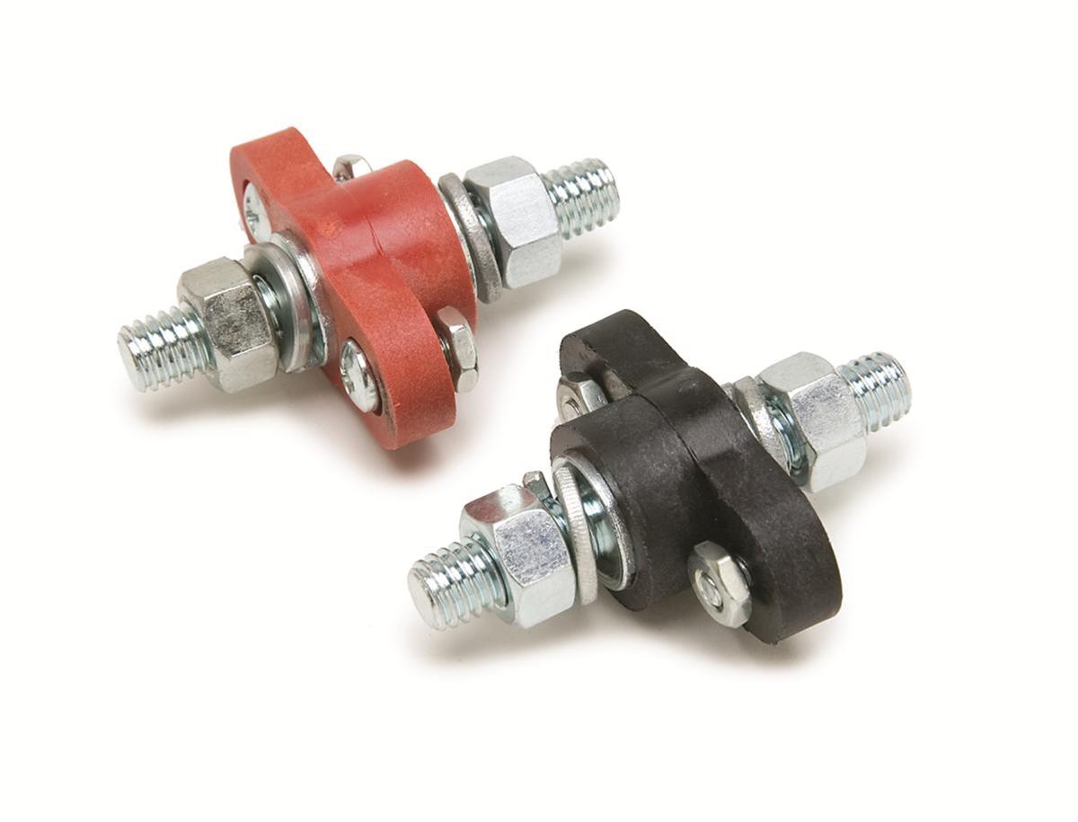
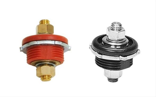
Ensure the shunt does not make physical contact with the metal. Some shunts have a phenolic plastic base (that's ok) but other shunts have no non-conductive bases. If it touches the metal, it will make it negative.
The aluminium is easy to work & cut, just take your time and remember to file off any sharp edges and such.
For the threaded rod. Any place like a Homedepot will stock very cheap clear tubing in assorted sizes, sold by the foot. This is actually a very nice clean solution add cheap as chips.
Cell "faces" should not really make direct contact with a metal housing, it is best to have a protective non-conductive layer between the cells & metal casings.
*Cell Tops can heat up, especially if something goes wrong. If you are covering the cells, make sure it is non-flammable or that it won't melt onto the cells, leave airspace between cell tops and any cover used.


")