diy solar

diy solar

Plan for 50A 5th wheel install

That Tyco will work fine for the charge contactor. I just went with the BlueSea as we use a ton of them at work and like that it has a manual way to turn it on or lock it off if needed.

Here is some info on the charge/discharge enable/disable on the Multiplus.

I only have one contactor on the way, so I have to buy another one anyway. Not sure why the vendor said I only needed one.

Thanks, I will read that info over.
 
you're already spending the money on smart victron components. why not spend the $30 on a raspberry pi and have it control everything in a smart fashion compared to digital enables and contactors by a 3rd party component. no point of using 90s tech. plus you get the bonus of remote monitoring and control
 
you're already spending the money on smart victron components. why not spend the $30 on a raspberry pi and have it control everything in a smart fashion compared to digital enables and contactors by a 3rd party component. no point of using 90s tech. plus you get the bonus of remote monitoring and control
The contactors are for the REC active BMS on my battery bank, nothing to do with the Victron components. I will use my laptop to Bluetooth to the Victron components, so I will have remote monitoring and control.
 
That Tyco will work fine for the charge contactor. I just went with the BlueSea as we use a ton of them at work and like that it has a manual way to turn it on or lock it off if needed.

Here is some info on the charge/discharge enable/disable on the Multiplus.


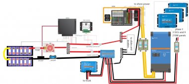
I think I am getting closer now. See any issues? I didn't put in the line for the charge/discharge enable/disable yet, but I know about it and will read the info you posted above. Also, if you are wondering about the 2 shunts, I got one with the REC that feeds the REC, and I already had a smart shunt to get bluetooth readings - there is no way to wire the BMS to the smart shunt, so I was told to just put them both in series. Let me know what you think. Thanks!System plan 2.jpg
 
No issue with series shunts.
Just to comment here: if you want an idea of the data you can get from the victron using a raspberry pi with internet access, you may enjoy my fridge testing thread:

All the graphs I stuck in there are using a pi (and usb dongles to talk to the victron gear) and connect to the free vrm portal that victron provides.
I love that you have a precharge handler there, this is great. That thing is overpriced IMO but plug and play at least.
I suppose I should just make up some precharge relay boards and sell em, it seems like everybody needs one anyway.

Oh, I almost forgot. Consider making up a bypass switch for the contactors. If one fails open or closed, you want to be able to manually bypass it with on or off. This is pretty easy with a blue seas dual battery connector. Add a button with a big resistor 10ohm for 12v IIRC for precharging before you flip the manual switch when/if you need it. Replacing a contactor on the road sucks - you wont have one, prebuild the bypass for happy camping.

You don't actually NEED a victron busbar unless you really want one. All the charge sources only need like 10awg and the only big fat wires will be the multiplus. (You will probably want two 2awg or similar going to that thing)
I don't see fuses on your multiplus runs. Get some ANL fuse holders with fuses. For double wires to it, just split the victron spec'd fuse value in half and use two of them, one on each wire.

You don't need a contactor for your charge sources. All of the ones you are spec'ing offer disable controls. No need for a disconnect there. Your BMS can drive an optoisolator pack that can enable/disable all of those.

I presume you have dual AC legs in your power panel?
You have a couple options there. Here's what I did:

the win there is that I can use a full 50a feed when I want to, or use my inverter for everything.
 
Last edited:
I think I am getting closer now. See any issues? I didn't put in the line for the charge/discharge enable/disable yet, but I know about it and will read the info you posted above. Also, if you are wondering about the 2 shunts, I got one with the REC that feeds the REC, and I already had a smart shunt to get bluetooth readings - there is no way to wire the BMS to the smart shunt, so I was told to just put them both in series. Let me know what you think. Thanks!View attachment 47571

You want the pre-charge on the charge contactor as the Multi is the one that needs to be pre-charged. Not sure if the Orion DC to DC has big output caps that need it as well; the SCC's typically do not.

You can also get rid of the bus bar right off the mechanical disconnect and just use two cables on the output lug to each contactor. A couple less connection points to worry about. The BlueSea disconnects are built to handle a couple lugs on the input/output.

I see the fuse on the output of the discharge contactor but it's probably sized for the entire bus so make sure you have correct protection for each load.
 
you're already spending the money on smart victron components. why not spend the $30 on a raspberry pi and have it control everything in a smart fashion compared to digital enables and contactors by a 3rd party component. no point of using 90s tech. plus you get the bonus of remote monitoring and control

How do you get supported canbus access on the RPI for cheap? Also the VE.Direct to USB connectors add up as well. Last time I looked it was almost as cheap to just buy a Cerbo - but if a cheaper way I am all ears!
 
You want the pre-charge on the charge contactor as the Multi is the one that needs to be pre-charged. Not sure if the Orion DC to DC has big output caps that need it as well; the SCC's typically do not.
Nice catch, I totally missed that!
 
The contactors are for the REC active BMS on my battery bank, nothing to do with the Victron components. I will use my laptop to Bluetooth to the Victron components, so I will have remote monitoring and control
The data output from the multiplus is basic with no history. By adding a $30 raspberry pi you allow your victron components to work together. You also get your data in one location and don't have to connect to individual SCC.

How do you get supported canbus access on the RPI for cheap? Also the VE.Direct to USB connectors add up as well. Last time I looked it was almost as cheap to just buy a Cerbo - but if a cheaper way I am all ears!

Ve direct to usb are normal 3.3v ttl adapters. $12 on amazon. The ve bus adapter is pricey but that's only one.

So under $150 for the rpi vs $300 for the cerbo. If you want the touchscreen then it's $60 vs $200
 
You want the pre-charge on the charge contactor as the Multi is the one that needs to be pre-charged. Not sure if the Orion DC to DC has big output caps that need it as well; the SCC's typically do not.

You can also get rid of the bus bar right off the mechanical disconnect and just use two cables on the output lug to each contactor. A couple less connection points to worry about. The BlueSea disconnects are built to handle a couple lugs on the input/output.

I see the fuse on the output of the discharge contactor but it's probably sized for the entire bus so make sure you have correct protection for each load.

Ok, they had it on the discharge contactor in the ABMS manual. I wondered about that. Guess they were showing it with the large load (inverter) being on the discharge, but we have it on the charge since it does both...

Will get rid of the busbar.

Yes, I didn't show the fuses for each load. For the slides and levelers, I am going to probably be able to reuse some of the factory wiring and fuse holders/fuses. I will sort all of that out once I dig into the spaghetti bowl...

What about what willo says below about not needing a contactor for the charge sources? Doesn't that go against what you both said about needing the precharge on the charge contactor?
You don't actually NEED a victron busbar unless you really want one. All the charge sources only need like 10awg and the only big fat wires will be the multiplus. (You will probably want two 2awg or similar going to that thing)
I don't see fuses on your multiplus runs. Get some ANL fuse holders with fuses. For double wires to it, just split the victron spec'd fuse value in half and use two of them, one on each wire.

You don't need a contactor for your charge sources. All of the ones you are spec'ing offer disable controls. No need for a disconnect there. Your BMS can drive an optoisolator pack that can enable/disable all of those.

I presume you have dual AC legs in your power panel?
You have a couple options there. Here's what I did:

the win there is that I can use a full 50a feed when I want to, or use my inverter for everything.
I already have the Lynx, and the fuses go in there. I will be running 4/0 to the Multiplus.

I do need a contactor on the charge side - that is where you both said to put the precharger. I will also use the optioisolator as jwelter99 recommended above.

The Multiplus is the new MultiPlus-II 12/3000/120-50 2x120V - it feeds both legs of the 50A power panel.
 
Ok, they had it on the discharge contactor in the ABMS manual. I wondered about that. Guess they were showing it with the large load (inverter) being on the discharge, but we have it on the charge since it does both...

Will get rid of the busbar.

Yes, I didn't show the fuses for each load. For the slides and levelers, I am going to probably be able to reuse some of the factory wiring and fuse holders/fuses. I will sort all of that out once I dig into the spaghetti bowl...

What about what willo says below about not needing a contactor for the charge sources? Doesn't that go against what you both said about needing the precharge on the charge contactor?

I already have the Lynx, and the fuses go in there. I will be running 4/0 to the Multiplus.

I do need a contactor on the charge side - that is where you both said to put the precharger. I will also use the optioisolator as jwelter99 recommended above.

The Multiplus is the new MultiPlus-II 12/3000/120-50 2x120V - it feeds both legs of the 50A power panel.
OK... Lemme splain. :)

1) The precharge circuit is to precharge the capacitors in the Multiplus when it is connected. Period. You don't have anything else that would require it. Since you cannot separate the charge/discharge of the multiplus, it goes onto the discharge contactor.

1a) If you do install a contactor on the charge sources, then sure, you may want to add a precharge as insurance. You could possibly create a scenario where you arc. But seriously you don't need a charge source contactor if you just use the enable function that victron provides on most of their gear. On my system, everything, including the tow charge controller has it.

2) Regarding your slides, mine has 30a resetting breakers from the factory. This is a good way to go since if the motor loads up it can trip, but then reset and work again. (Mine tripped the other day, trust me it was better to not need to crawl around and hope I had a fuse.)

3) For your charge sources except the multiplus, you do not need a pre-charge/contactor, provided they have/or support an enable feature, which the victron gear does. (check the models of your SCC, it can vary but most of the ones above base do)

4) I think you mentioned something about your brake controller but I don't wanna scroll right now - I use a small SLA battery to run my breakaway system. Account for this in your design. If your battery has disconnected, those brakes need power in case of trailer disconnect. I added a small breakaway charge controller (like $5) to charge it when towing.

Finally, if you haven't bought a BMS yet, you may want to consider the electrodacus SBMS0.
 
I like it because it's open source and has a good community behind it. This is certainly a personal preference thing.
 
OK... Lemme splain. :)

1) The precharge circuit is to precharge the capacitors in the Multiplus when it is connected. Period. You don't have anything else that would require it. Since you cannot separate the charge/discharge of the multiplus, it goes onto the discharge contactor.

1a) If you do install a contactor on the charge sources, then sure, you may want to add a precharge as insurance. You could possibly create a scenario where you arc. But seriously you don't need a charge source contactor if you just use the enable function that victron provides on most of their gear. On my system, everything, including the tow charge controller has it.

2) Regarding your slides, mine has 30a resetting breakers from the factory. This is a good way to go since if the motor loads up it can trip, but then reset and work again. (Mine tripped the other day, trust me it was better to not need to crawl around and hope I had a fuse.)

3) For your charge sources except the multiplus, you do not need a pre-charge/contactor, provided they have/or support an enable feature, which the victron gear does. (check the models of your SCC, it can vary but most of the ones above base do)

4) I think you mentioned something about your brake controller but I don't wanna scroll right now - I use a small SLA battery to run my breakaway system. Account for this in your design. If your battery has disconnected, those brakes need power in case of trailer disconnect. I added a small breakaway charge controller (like $5) to charge it when towing.

Finally, if you haven't bought a BMS yet, you may want to consider the electrodacus SBMS0.

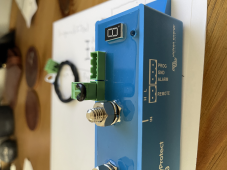
This is all good advice and as long as what is in #3 is true you are fine. Most all Victron gear has a remote enable switch - it is typically a 2 pin connector that comes with a wire bridge between the two pins. These pins are H and L. You can use these to enable/disable charging without needing a contactor to physically disconnect them. The only challenge here is not all other equipment have a remote control and then the contactor is the only easy way. But if everything does it's an ok way forward.

As for the Multiplus I prefer it on the "charge" side as in all the systems I've ever assembled the charge limits are higher than the discharge limits temp wise. You can charge down to 5C most packs, but discharge down to -10C at modest C rates. I also don't like big discharge loads when below the safe charge temp; of which the MP is the biggest; as you can not recharge the pack if depleted. I rather go without my AC loads then risk that. Your use and expectations might be different.

Attached is a picture on a BP that shows this remote connection, but it is the same on most Victron equipment.
 

Attachments

  • tempImageyUFiLV.png
    tempImageyUFiLV.png
    1.9 MB · Views: 5
Last edited:
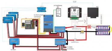
So, I reconsidered some things and went back to the drawing board for the whole thing. I decided to add the Cerbo GX and use the canbus for the BMS to talk to the Victron components. I also added the trickle charge from the MP to an AGM battery for the breakaway. Below is where I am at the moment. I think I have covered everything now.


system 3.jpg
 
Dude! Sweet! and then . . . and then and then and then and then and then . . . no more and then! He's covered everything now.

Time for the repro :D
 
Looks good, the only nit I have is the yellow cable in the battery.

Have you thought about this layout?
 

Attachments

  • battery_v2.pdf
    20.9 KB · Views: 20
Looks good, the only nit I have is the yellow cable in the battery.

Have you thought about this layout?
Yes, that and others. 1/4" tinned copper plate for that is gonna be hella expensive... and I was concerned that might be a problem with expansion and contraction on the studs...
 
Yes, that and others. 1/4" tinned copper plate for that is gonna be hella expensive... and I was concerned that might be a problem with expansion and contraction on the studs...

I'd go with 1/8th. I'm not worried about expansion and contraction if you keep cell voltage at or below 3.5V.
 
I'd go with 1/8th. I'm not worried about expansion and contraction if you keep cell voltage at or below 3.5V.
Still $137 for one 12" x 12" piece of plate (not tinned)! I already will have $130 in a 1/4 x 1-1/2 x 72" for the other bars.
 
Still $137 for one 12" x 12" piece of plate (not tinned)! I already will have $130 in a 1/4 x 1-1/2 x 72" for the other bars.

Where you buying as seems high? I can get 1 inch by 1/8th copper with silver plate for about $8 a foot. For 5 inch wide for the "spanner" it's $50 a foot; but a foot gets you all you need.

Perhaps as we both want the same bus bars we should hit up @Lt.Dan for a group buy using his fancy plasma cutter. Perhaps others?
I was looking where many on here recommended - online metals... I would definitely be in for a set of pre-made bus bars if you know someone who can cut them. I'm looking for 600A capacity...
 

diy solar

diy solar
Back
Top