diy solar

diy solar

Cinergi's 28 kWh / 4 kW Solar / 10 kW inverter RV build

its not just the extra wiring, its the extra fusing, and the other extra complexity.

chargery -> time delay cap circuit -> contactor
vs
chargery -> ssr
batt -> ssr -> contactor
batt -> contactor
plus fusing

I guess I was assuming "time delay cap circuit" would be various wires, not a PCB or such :)

It’s pretty important to me. 24v 560ah bank with 1500 watts solar. powering mini split, fridge, water pump, led lights, various electronics, 2 burner induction stove, air fryer.

As an example, the Gigavac MX14 is 2.8W but requires 3.9A pick-up current. The MX11 is 8 watts but only requires 0.68 amps ever. So that's a 5 watt difference or 120Wh/day or 0.8% per day of a 14,784 Wh battery bank. Would that work? (not sure what your peak DC load is)
 

That’s good info on those different gigavacs. Thanks for that. Food for thought.

As for a time delay. Very simple pcb linked below well within the specs of what I need. chargery -> capacitor -> pcb-> contactor. No extra fusing or wire sets required. BMS enables charge/discharge, cap begins charging and pushes power through to pcb, timer starts, 5 second delay would be plenty to charge the cap (see RC time constant), done.

XINGYHENG 5Pcs 12V NE555 0-10 Seconds Delay Timer Switch Module Constant Current Regulator Timer Delay Converter for Automotive Control System Electrical Equipment https://www.amazon.com/dp/B07Q27L1WK/ref=cm_sw_r_cp_api_glt_fabc_H8C7PDKFAYQ7GKCE8VGN

All of that said, an inline resistor doesnt seem like a bad idea (chargery -> resistor -> capacitor) assuming its not too small to prevent the needed power from flowing. I’m thinking more along the lines of limiting the inrush to the capacitor (if its even necessary). Im thinking a 25v 1000uF capacitor. Thoughts?

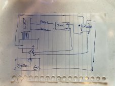
Ah, so when chargery turns on it immediately does 2 things: 1) starts charging the capacitor (which is parallel to the contactor but before the timer & contactor) and 2) starts the timer which ultimately closes a 0-resistance connection between the battery and the contactor with the capacitor (and maybe resistor) in parallel so that most of the current is taken from the capacitor. Gotcha.. sounds like a reasonable plan. When the BMS calls to shut off the relay, power is removed from the capacitor and timer circuit so I assume the contactor would also lose power? Would DC voltage coming from the inverters accidentally keep the contactor running? Like this? (technically you should have fusing here, too... any wires coming from the battery should be fused - e.g. the + to the contactor)

IMG_9677.JPG
 
n
Ah, so when chargery turns on it immediately does 2 things: 1) starts charging the capacitor (which is parallel to the contactor but before the timer & contactor) and 2) starts the timer which ultimately closes a 0-resistance connection between the battery and the contactor with the capacitor (and maybe resistor) in parallel so that most of the current is taken from the capacitor. Gotcha.. sounds like a reasonable plan. When the BMS calls to shut off the relay, power is removed from the capacitor and timer circuit so I assume the contactor would also lose power?
you assume properly.
Would DC voltage coming from the inverters accidentally keep the contactor running? Like this? (technically you should have fusing here, too... any wires coming from the battery should be fused - e.g. the + to the contactor)
Not sure how voltage from inverter would keep contact open. the coil circuit for the relay is powered by the BMS charge/discharge cap/time-delay circuit. there is no secondary control circuit like with an ssr. the most that could be said would be that the capacitor might hold the contact open for milliseconds after bms removes power.

no there will not be fusing between the battery and the contactor. the contactor comes immediately off the battery, then goes through a class-t 200a fuse then goes to the disconnect switch.

here is a thread on my system
Thread 'Solar rv electrical system - final checks'
https://diysolarforum.com/threads/solar-rv-electrical-system-final-checks.24700/


i may be over-thinking this, though. chargery is capable of separate and common port. with separate leads for each. if each is capable of 3a, and if they both operate together when configured for common port, then that is effectively 6a available in parallel. i need to send another question to Jason.
 
Not sure how voltage from inverter would keep contact open. the coil circuit for the relay is powered by the BMS charge/discharge cap/time-delay circuit. there is no secondary control circuit like with an ssr. the most that could be said would be that the capacitor might hold the contact open for milliseconds after bms removes power.

Yup, you're good - was thinking out loud before I drew the diagram.

Great question on common port - if that truly gives double the amperage, that would be awesome.

The only REAL reason I have a 3a fuse is because Orion BMS calls for it. It does protect the wire to the contactor, too but I'm not sure I would have put a fuse there if the BMS didn't need it.
If i were running other separate wires for a ssr or secondary contactor, then i would definitely have fused those leads. since the power source is the chargery and not the battery bank capable of 20k amp short circuit current, i am not so worried. id be willing to bet the ceramic fuses are costly. not that i wouldnt be willing to do it
 
If i were running other separate wires for a ssr or secondary contactor, then i would definitely have fused those leads. since the power source is the chargery and not the battery bank capable of 20k amp short circuit current, i am not so worried. id be willing to bet the ceramic fuses are costly. not that i wouldnt be willing to do it

FWIW, about $14 for 10 (McMaster-Carr) plus about $2 for the holder.
 
I guess I was assuming "time delay cap circuit" would be various wires, not a PCB or such :)


As an example, the Gigavac MX14 is 2.8W but requires 3.9A pick-up current. The MX11 is 8 watts but only requires 0.68 amps ever. So that's a 5 watt difference or 120Wh/day or 0.8% per day of a 14,784 Wh battery bank. Would that work? (not sure what your peak DC load is)
Thanks again for this info. It encouraged me to go back to the gigavac site and check out their mx line.

I ordered 2 of these: https://www.gigavac.com/products/mx12sa
 
Mr. Cinergi,

I have two questions which I would love to hear your thoughts on.

1) Since you do not have a generator, why quattro over multiplex?
2) Do you have more batteries than you need by a large factor
3) If you had only 120 volt needs would you have gone with a single larger 10k quattro?
4) Are you happy with what you did? Would you change anything?

(following on the jokes) I have two answers!

1) Quattro's I chose for several reasons: 48v, 5kva per leg, and multiple input *in case* I did a hard-wired generator (I would have done a permanent generator if it weren't so expensive; I'm still on the fence). MP at 3kva (2400 watts) per leg was too close for comfort, plus of course the 48v requirement.
2) I'm finding that 28 kWh is a good size - I can get away with 2-3 days of rainy conditions before I have to consider plugging in / generator. I typically use 25-30% overnight .. if the battery was half the size, that would have been 50-60 overnight which I wouldn't be happy with. If anything, I would add more batteries because I frequently "throw away" solar energy due to full battery
3) Based on what I know now, I would have gone with a single 5k or maybe 8k .. 10k is too much. I typically use < 2kW and my highest peak was like 4kW
4) Very happy; the only thing I'd change would be physical arrangement/location because I'm having trouble cooling the RV basement (batteries are getting too warm) and having only one access point to the basement makes getting at stuff in there a PITA
 
When you say 5k or 8k are you talking single quattro with auto transformer?

My answer #3 is in response to the question about the hypothetical situation where I only needed 120v in the rig -- so no, no autotransformer in that case; just a single Quattro providing only 120v. But I need 240v in the rig and I also wanted to be able to use 120v or 240v shore power.

I will add, however, that I could probably have just limited myself to 120v shore input (15/30/50 amp single leg) and gone with a single quattro with an AT on the output side. I suppose that would be a modification to the design that I would highly consider. 50 amps at 120v is more than enough juice. Would have saved a lot of money and a fair amount of inverter idle waste.
 
Thank you for more than answering my two questions

Do you mind telling us (off topic apology) what program you used to prepare your diagram. I am going to copy much of your HARD work and thank you very much. If you want and are willing to share your diagram in its original base format it would save me a few hours of work and would be worth some serious good wine. Pl let me know if that is in the cards.
Rob

Thanks!

I used draw.io ... here's the raw file: https://www.dropbox.com/s/3bv1or0ir7qvjvx/NH Electrical V3.drawio?dl=0
 
I can't remember where this question was previously asked, months ago .. but, I just tested what happens when connecting to 208 (the result of connecting to "240v" power from 3-phase commercial source). Only 1 of the Quattro's connects. It does NOT pass through both legs. It's possible if I lowered the minimum AC voltage that it would but I was OK with it connecting to only 1 leg. I really don't need more than 50 amps at 120 anyway as I mentioned before. The progressive EMS passed through both legs just fine, but the Quattro's accepted only one of them.
 
That's an interesting find, I haven't read on to your point since I went with the single Quattro (on YOUR advice ? )

So you think it's initial setup setting or based on demand? I'm interested to know what you find out.
 

diy solar

diy solar
Back
Top