diy solar

diy solar

Finally found a LiFePO4 BMS with Low-temp Charging Protection

I am also using the $6 iOS pro version. I see on yours it shows 1 cycle. Was that a full cycle of the battery? Because I have only gone down maybe 50-60% and there was no cycle count showing? It seems to only count full cycles, maybe down to 80% or more? That is what the parameters show currently for cycle capacity. Or do you set cycle capacity on the parameters to your estimated normal level of discharge?
HMMM .... mine shows 7 cycles .... and I've only done 3 deep discharge cycles while capacity testing. I'm not really going to be using it regular til spring, so I don't know what constitutes a cycle either.
 
HMMM .... mine shows 7 cycles .... and I've only done 3 deep discharge cycles while capacity testing. I'm not really going to be using it regular til spring, so I don't know what constitutes a cycle either.

In the app parameter menu mine was set at 80% cycle capacity as default. Wonder if that has something to do with cycle counting? On your deep discharges did you do others also that may not have been as deep but have been counted as below the set parameter threshold? That may be what was counted. ?
I don’t want to change my parameters too much as I’m not very sure what does what and don’t want to get too far out of my tech knowledge. So listening to those in the know on these app settings.
A09804EC-FBB1-4AF3-B5BA-D6E1049E7966.png
 
@MrNatural22 I don't think I have done 7 discharges that would have been to 80% capacity .... mine is set the same by default. I thought somehow it may have been counting a cycle when I wrote a new paramater, but just tried that and it didn't count a cycle.
It did mess up the % charge when i did that. I will fully charge it now and see if that causes it to see a charge cycle. It went from 95% to 68% when I modified a paramater slightly.
 
@Bob B I changed my cycle capacity down to 50 and I’m discharging down to just below 47. When it gets there I’ll hook the PV back to charge up tomorrow and see if it registers 1 cycle when topped of. Also if as yours did see if the charge % has changed. ?
 
Last edited:
Hello everyone,

Sorry for the very long post, but after reading this entire thread, I thought I'd explain my thoughts on what is being discussed and how I plan to use this BMS in my project.

I have received 3 of these 100 Amp Smart BMS devices for my project. I ordered mine through ebay, from China and they took a few weeks to show up. Ordered them right after watching Will's first video on the $555 battery build. I needed that cold temp shutoff and loved the bluetooth programming option.

I've read this entire thread after building my first complete battery and spending some time with the app on my Samsung S7 phone. Just knew that a thread like this had to exist on this forum. I have a few things to add to the conversation. I also need to learn more about the app and the options we can control throught its interface. So far, I don't see a summary of all of the parameters that we can adjust; has anyone compiled one or found documentation for this BMS we can refer to (in english)?

I am using CALB lithium iron phoshate 130 Ah cells purchased 8 years ago for an EV project that I completed, ran for 16K miles and then took off the road, due to insurance costs, and OEM EV advancement. I am recycling a lot of equipment from my EV project to build an AC/DC system for my camper.

1. Why can't batteries like this be connected in series? Maybe I missed something... I assume that I can't connect these 3 batteries in series because that means all of the system's current would have to pass through each BMS. In my EV I had effectively, one big 144 VDC battery that routinely put out 300 amps for short periods of time. There was no BMS directly in the circuit like we see with this BMS. We all know the size of the wires that come with this BMS have limited current carrying capacity. Is my assumption correct?

2. I saw the mention of using seperate charge control and seperate discharge control. I don't think I can do that. I am treating the three batteries that I am building as distinct batteries with there own internal controls. As if I had purchased 3 Battleborn batteries.

My intent is to connect them in parrallel for a max output from each of approximately 61 amps. Which, I probably need to bump up a bit which means adding a third 10 gauge wire to each side of each BMS to account for the worst-case senerio which is driving a 2000 watt Xantrex inverter and all of the normal DC loads (water pump, tv, lights, furnace) in my camper. I expect to be at max output only when the microwave, or something else is running in the camper. The primary need for AC while boondocking is for my wife's sewing machine which has very low power requirements compared to that microwave. Certainly appropriate load management will play into the picture.

3. How do I get around having two devices trying to do the same thing? Well, at the moment, I plan to configure the BMS to disconnect from charging at something like 15 volts but configure my Victron MPPT 150v/50 amp charge controller to consider 14.6 as the max battery voltage. The charge controller will also monitor battery temp with the Victron temp sensor bluetooth device. I consider the BMS Low Temp feature as a good redundancy feature. I also plan to use the BMS as my low voltage cutoff device, set to something like 12 volts. I had originally included a Victron 220 battery protect in the system but after reading another thread about applying reverse current to that device, I believe I've already toasted it, so it has to come out of the circuit. (how annoying!)

4. For state of charge monitoring, I will of course use the app on my phone with a hardware backup. I have an amp hour counter and display from my EV project that I used very successfully as my 'fuel gauge' to make sure I was VERY gentle with the batteries (thinking SOC). Positioning the shunt for my amp hour counter means that all charge and discharge current must pass through it's shunt. That device can display the battery pack voltage, current loads, and accumulated and consumed amp hours.

5. Battery temp control. Seems that cutting off charge at low temps is covered. However, in the winter I may want to charge as well. In my EV, each battery box had a custom AC heating mat using material that I found on a web site specializing in keeping pets warm. Pets like lizards and turtles so it couldn't get above 65 degrees F. I programmed an Arduino to monitor the temps and warm the batteries when the EV was parked in my garage, connected to 110 VAC solely for the purpose of keeping the cells warm enough. Now, with the option for a 12VDC heating mat, I will likely go that way if needed. I am building a custom weather tight aluminum battery box for the front of my camping trailer to house all of this equipment and can insulate that box a bit, if I need to. However, I'm more concerned about ventilation because my plan is to start snow-birding from Northern Idaho to Arizona. But even in Arizona, I understand we might see temps at or near freezing routinely, at the start or end of the season. I really don't expect to see uppper temps in the battery box that might cause a problem. However, I will monitor that and adjust as needed... something like this is never finished... where is the fun in that?

I still have a number of issues with this project to address. Such as handling AC charging. Hoping that might be as simple as switching to a converter intended for this batter chemistry.

If you have made it this far, please let me know if you see any fatal flaws in my design or have any comments to share.
 
8s not available yet. Tom said he is still waiting for that shipment. Tom and I were messing with it last night and testing every aspect of this bms. We have been trying out various bms for months now. We really though the daly would have the low temp cut off on the new model with the temp sensor.

And 16s model, I am not sure about. You could use 2x 8s models in series for 16s. That would work.
Will, first of all, thanks for spreading the knowledge! I am new to using BMS's and am building a 24v battery bank. Does the 8S BMS you mention have low voltage cutoff, balancing, etc. or do I have to install a separate balancer and battery monitor. I wish I could find a user manual or some documentation on these units.
 
@MrNatural22 .... It looks to me like they are tracking the discharge amps to determine a cycle. I discharged mine to 50% and then recharged it. While discharging again it increased the cycle count by 1 before I got to 50% discharge again.
 
@Bob B I tried a to discharge down to 47% and had charge cycles set to 50 but didn't see a cycle registered after charging back up this morning.? It was down to 47% under load and with it rising back up after resting over night maybe it only counts resting capacity remaining? Humm. Ill try again to bring it down to a lower capacity next time and see if that works. What ya think??
 
Any way to control a relay with these? Any reason to besides higher current ability?

I don’t know much about moffsets and their longevity w/r/t current or failure mode.

also, see my earlier post basically asking how trustworthy this bms is (and similar ones) when used with appropriate charging sources -should you have a separate low/high voltage cutoff?
 
I purchased one of these BMS' from battery hookup for a headway 4S4P I built. Getting connected wasn't easy though it wasn't too bad either. I didn't need any passwords or anything special other than the apk file and a few attempts to connect. Being a newbie in this area, the parameters have me struggling. Can anyone suggest what the optimal settings should be set to? The cells are the headway 38120, 8ah and they are set up in a 4S4P configuration. I also have a 40 amp charger. It's up and running but I feel like I need to tweak the parameters. These are the options.
  • Overvoltage
  • Overvoltage release
  • Pack Overvoltage
  • Pack Overvoltage release
  • Undervoltage
  • Undervoltage release
  • Pack undervoltage
  • Pack undervoltage release
  • Discharge current (set at 100 amps for my application)
  • Cycle Capacity
  • Nominal Capacity
  • Open balance options (open or close)
  • Balance mode options (charge balance or static balance)
  • Balancing precision (default set to.0.05)
  • Galvan ometer (default set to 0.1 mR)
Any help would be greatly appreciated
 
Has anyone found a 200 amp version of this 4S BMS (or something very similar) for a 12 Volt system?
 
Has anyone ordered these directly from www.lithiumbatterypcb.com? I sent a few emails asking questions and haven't heard back. They could be backed up due to the Chinese New Year. It is a better price and you can get UART and RS485.
 
Hey, new question... where is the best place to position the temp sensor? I am building a 4S battery using CALM 130 Ah cells. I could tape the sensor to the side like Will did. OR I could feed the sensor down between the two center cells. My thought was that I'd get a better idea of the temp of the mass of the cells vs. the temp of the skin.

But, not sure if that is really a good idea or not. If the skin is close to freezing temp, then THAT is the time to shut off charging, rather than waiting for the center of the battery to get that cold.

Gee... maybe I answered my own question. Thoughts?
 
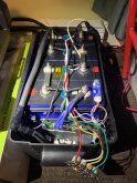
I taped mine on the QR code on the top, it's directly on the aluminium case and will have less chance of getting damaged.IMG_0989.jpeg
 
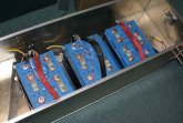
I just test fit my 3 batteries in the custom box I've built... they don't fit as expected after I added the all-thread to pull them together. My design evolves once again.
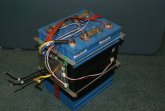
Pretty sure I'll just tape the temp sensor to the outside of the battery. The pic below shows the temp sensor placed between cells, but I'll move it to the outside of the battery.
Originally, the 3 batteries were going to fit lengthwise with the inverter and all the other bits crammed into that box. but now, looks like the inverter will live inside the camper and only circuit protection gear will be in the box. The box is designed to fit in the A-frame at the front of my camper, where the original FLA batteries sat.

sm_DSC06786.jpgsm_DSC06785.jpg
 
Oh, wanted to ask, when I parallel these batteries is it best to keep the cables all the same length between the batteries and the bus bar? I've read a few threads about keeping those cables the same length for the purpose of evenly distributing the load and charge between the batteries. That had never occurred to me before...
 
There is a lot of opinions around this.

No matter what, the most important thing is to make sure you have properly gauged wires with excellent crimps/connections. If you don't do this, the length is the least of your problems


Are you going to wire the 3 12 volt banks in series? If so, the most important thing is to keep everything as short as reasonably possible.

Are you going to wire the 3 12 volt banks in parallel? If so, there are a lot of opinions but not a lot of science to back them up. (This is true of some sources that are otherwise very credible and knowledgeable.)

I have seen a few different claims on the 'only way that works', they boil down to 3 claims

Parallel Option 1: It does not matter, just hook 'em up

Parallel Option 2: Tap the negative and positive from opposite batteries (In these pictures, each blue rectangle is one of your 12V banks)
1581182122702.png
Parallel option 3: Equal length wires to common bus bars
1581181919676.png

Which should you do? I go with option 2.

There is also a belief that you must keep the length of the cables going from the batteries to the rest of the system the same length. I do not believe this at all. In fact, I believe it is counter productive. If you make a cable slightly longer to 'match' the other, all you are doing is adding resistance to the round trip path.
 
Option 1 is crappy.
Option 2 is far better but not perfect if more than 2 batteries.
Option 3 is perfect but often hard to do in practice, so we choose option 2 most of the time.

There is also a belief that you must keep the length of the cables going from the batteries to the rest of the system the same length. I do not believe this at all. In fact, I believe it is counter productive. If you make a cable slightly longer to 'match' the other, all you are doing is adding resistance to the round trip path.

Yeah that's pure BS in DC (but it matters for high frequency stuff), you just increase the losses for absolutely no reason. Shorter is always better.
 
Shortest Same Length cable of the "Right Gauge" is always best but not tight so there is no movement, you need to leave a bit of play for shifting things around, and working on your gear. IF using a BUS topology same length cable is highly suggested. Its how I have been taught & trained over the decades.

All opinions on the internet are opinions and must be treated as such. Do what sounds & looks most reasonable & logical (pennies & dollars are moot) which does not compromise safety, quality or generally "good practices" and that is where your critical thinking comes into play.

Some will tell you to keep your DC wire separate (you get RFI and EM issues) or keep them as close to each other as possible (to cut generated external effects) which is what I suggest always. Simple to test, use an AM radio (that is if you can find one). Such interference can affect Cell Phones, Wifi, Bluetooth and more.
 
1. Does this BMS directly support CANBUS?
2. Can this BMS support CANBUS via a software interface such as on a Linux server (e.g., a Raspberry Pi)?

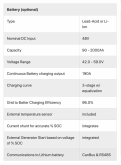
I ask because I'm starting to find solar charge controller inverters like the SolArk that say they require it.


For instance, from that Sol-Ark 8K, here is the screenshot:
Screen Shot 2020-02-08 at 11.56.08.png

The very last line says "Communications to Lithium battery": "CanBus & RS485".

So, I believe that means it needs CANBus over an RS485 connection.
 
Waiting for my two 120a units to arrive. Does anyone know the rated surge/overcurrent capabilities of these?

(I.e 135 amps for 10 seconds, 150a for 3s, etc).
 
I have the 120A units, but no batteries (damn you alibaba).

I have a similar question as Turd. The different Amp rating of the models just seem to have more 10g wires soldered in. What is the actual constant current and overcurrent capability for what time?

I suspect we will get no answer from the manufacturer, but the thing is made up of large mosfets. Do these mosfets have a rating that can be known by the markings or dimensions of them?

Can 120A be passed through continuously the 120A version, can 200A be passed through for 1s? etc...

Thanks x 1,000,000.
 

diy solar

diy solar
Back
Top