diy solar

diy solar

Connecting 20 wind turbines in series ?!

elvis_asaftei

New Member
Joined
Jul 5, 2021
Messages
257
I am searching for a way to connect 20 wind turbines to 48V battery bank, we have 10 wind turbines of 48v and 10 of 24V both are 10A wind turbines. Because distance is 100m to battery I wanted to connect output from wind controller in series and go to 350V input of standard MPPT solar inverter.
This seems it is not working because 2 or 3 of them always get locked and do not spin and also speed is not correctly optimized.

I wanted to have this setup to save a huge cost for 10 cables x 100m x 10amps

And use only 2 cables at 350V -400V with working mppt from 120v to 450V .

Anyone has any idea if this setup can work with addition of other diodes ?

My solution remaining to do ia that I will have 2 very large wires from 48V battery pack to the wind turbines and use one wind controller for each wind turbine .

Any suggestions how to connect 20 wind turbines ?
 
I do not think that is feasible. Especially at that distance I would much rather either just go solar or try to find a single really large turbine for sale locally. 20 turbines is 20x the amount of moving parts and 20x the maintenance.
 
I do not think that is feasible. Especially at that distance I would much rather either just go solar or try to find a single really large turbine for sale locally. 20 turbines is 20x the amount of moving parts and 20x the maintenance.
Hi, thanks for the the answer. Regarding wiring wind turbines in parallel to the same controller it is not possible with AC because wind turbines will slow each other because of different frequency and that it is not a synchronized wave. If you mean to add DC output from rectifier bridge to solar mppt input than both will have to run at same speed (this never happens to wind) and you will most of the time get power only from the one that is spinning faster, so not a good idea.
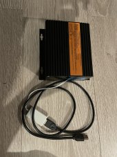
I have added one 48V $120 controller for each turbine that will optimize and boost voltage for each wind turbine. Picture below.

I have 4 wires of 100m long 40Amps max already installed from wind turbines to 48v battery bank so if nobody has any idea how to use maybe a CC or CV boost voltage with diodes I will have to run them all in parallel and that will work for sure, just cable cost is too high.
An important aspect for the controllers is that they are build to have battery voltage at a output so if they are put in series and one of them has above 60V it initiates the breaking of wind turbine and if voltage is lower it can not run because it shuts down every time wind turbine from it can’t produce voltage above 40V …

Any suggestion is welcomed. Thanks.
46A83D78-BA49-4287-B891-CA5A4B28F5D1.jpeg
 
I do not think that is feasible. Especially at that distance I would much rather either just go solar or try to find a single really large turbine for sale locally. 20 turbines is 20x the amount of moving parts and 20x the maintenance.
I already have filled the available roof space with solar and indeed solar is the best option because it produces a lot of energy in one year but wind is complementary because when there is a cloudy week usually there is wind day and night and wind will compensate the lack of sun for weeks sometimes.

How can we use wind controllers together with CV and CC voltage boosters with additional diodes and capacitors to make this work in series and feed to solar MPPT a series of 120V to 450V and not directly to batteries in parallel because I can safely go from 120V to 450V but not from 40A to 160A as I need for parallel. Also I consider safer to go through the inverter and not hook directly batteries output to entire 100m because of instant discharge from batteries in case of a short , even if I use fuses, in case of current leak it is not safe for battery bank.
 
Now that you mention it. If you were to put a DC-DC boost converter on the output of each turbine's rectifier, and set them all to the exact same voltage, then put them all in parallel, the load should spread quite evenly. The problem would be finding a boost converter that can turn your 48v into something high enough to be a meaningful difference. I know there's some of those chinese ones that reach up to around 80V and cost like $20 each, but it's probably not worth it.
 
Now that you mention it. If you were to put a DC-DC boost converter on the output of each turbine's rectifier, and set them all to the exact same voltage, then put them all in parallel, the load should spread quite evenly. The problem would be finding a boost converter that can turn your 48v into something high enough to be a meaningful difference. I know there's some of those chinese ones that reach up to around 80V and cost like $20 each, but it's probably not worth it.
Yes, it must be between 10A to 20A input and boost from 50V to minimum 120V and more is better, but they must sustain constant voltage of 40V - 60V to power the wind co troller ( I have seen that controller seems to power on quickly but not sure if thousands of power cycles if it is not constantly powered can affect it in any way).

Is it possible to use 2 x DC-DC boost in parallel at input ( wind contoller output) and in series at output so to have 80v x 2 = 160V output ? (5A input to 2,5A output for each).

I do like to have graphs and production on my phone from solar inverter and I will have that for wind too, so having this will bring many benefits and less problems if it will work.
 
Now that you mention it. If you were to put a DC-DC boost converter on the output of each turbine's rectifier, and set them all to the exact same voltage, then put them all in parallel, the load should spread quite evenly. The problem would be finding a boost converter that can turn your 48v into something high enough to be a meaningful difference. I know there's some of those chinese ones that reach up to around 80V and cost like $20 each, but it's probably not worth it.
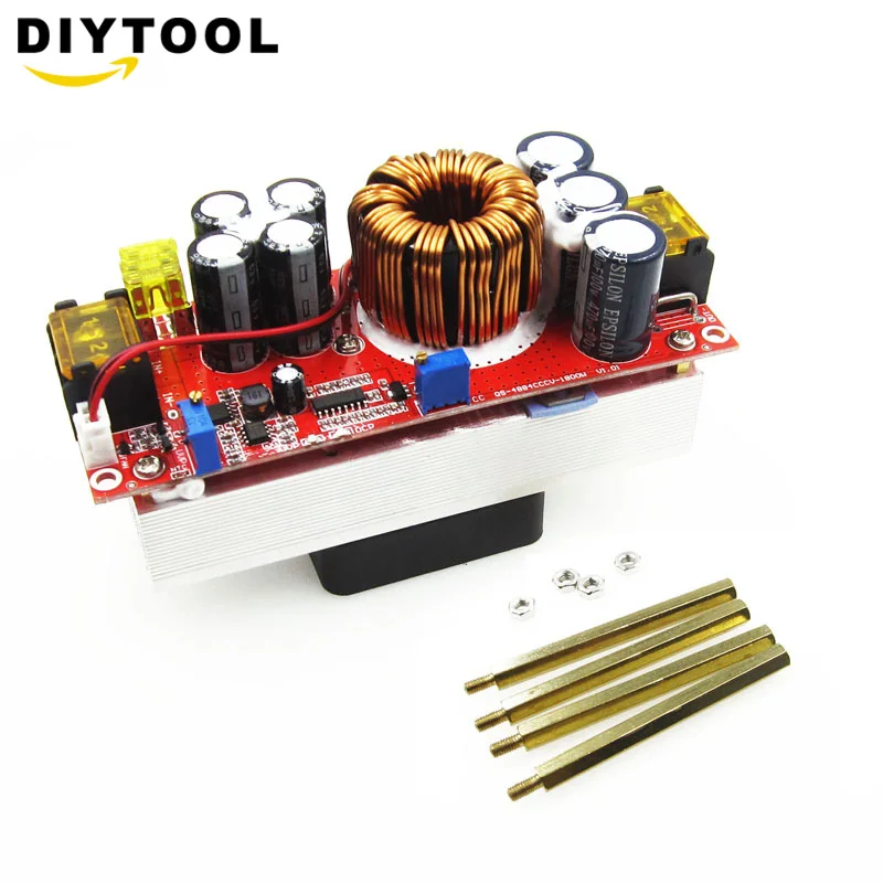
Will this one work to put 2 in series and same input a specified previously?

US $15.77 22% Off | 1800W 40A CC CV Boost Converter DC-DC Step Up Power Supply Adjustable Module DC 10V-60V to 12V-90V DIY kit Electric Unit Module
 
Maybe you could "parallel" them all into a local battery, run an inverter from that, transfer 240V to your main bank and charge it from it?
If charging is all you need, a cheap inverter will do.
As specified above cable costs for 200A instead of 40A for 100m in length is what matters and also lack of monitoring from mppt inverter with WiFi
 
Right, but if you transfer at 240V, you need a thinner cable than at 48.
And once you have AC, you can use a simple transformer to make it a much higher voltage - and re-transform it on your side.
 
Right, but if you transfer at 240V, you need a thinner cable than at 48.
And once you have AC, you can use a simple transformer to make it a much higher voltage - and re-transform it on your side.
Think a little , not possible to
Combine 20 x three phase AC to a single wire of 100m in length !
 
What I was thinking was to charge one battery. Where the turbines are. From that battery, make 240V with an inverter.
It can be a cheap square wave one.
Transfer the 240V (or more) to your installation, charge your batteries with those. Which is what I wrote.
What is not possible about that?

[EDIT] Obviously, you would feed all the separate charge controllers of the turbines into the "local" (call it "remote", the one where the turbines are) battery. Very possible :·)
.
Not possible at all, batteries are inside house , wind turbines 100m away, cold does not allow charging at negative Celsius temperature. Also loss is at 20% with so many conversions.

Waiting for opinions about the DC-DC voltage booster from 58V of wind controller to 90V than use 2 in series with the same input to have 180V than send 180V instead of 50V to the wires to solar MPPT that will charge the 48V battery bank and offer battery management and also WiFi monitoring of all production.
 
You can't put boost converters in series, they're not isolated. You'll just short them out.

Really the only way I see it working properly is if you just use the correct cables.

200A is way too much current to be carrying for 100 meters. Personally it were me I would cut my losses and try to find something else to do.

If you only used rectifiers you should be able to put them in series, but you lose all the protection that the controllers give, and of course if 1 turbine stops you lose not only the voltage of it but also the 2 series diode drops, so losing only 2 turbines drops the voltage by probably over 100v.
 
I mean another battery. Dedicated. For the purpose. Where the turbines are. A DC-DC voltage booster is basically a mini-inverter + a rectifier.
Without a local (remote, dedicated, whatever) battery the whole thing would be unstable anyway. It wouldn't have to be big, just set a low-voltage disconnect if the turbines stop charging.

It's really simple, actually. If you really don't want to understand, OK, don't.
 
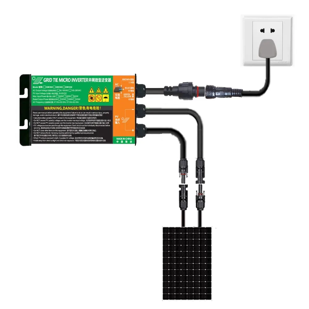
You could also use grid tied inverters and tie them to your grid. But obviously won't be able to charge batteries with the power. Something like
US $46.77 21%OFF | 300W 350W 500W 600W 700W Solar PV Grid Tie Micro Inverter MPPT DC26V-46V Solar Input AC110V-240V Output Home Solar On Grid
 
You can't put boost converters in series, they're not isolated. You'll just short them out.

Really the only way I see it working properly is if you just use the correct cables.

200A is way too much current to be carrying for 100 meters. Personally it were me I would cut my losses and try to find something else to do.

If you only used rectifiers you should be able to put them in series, but you lose all the protection that the controllers give, and of course if 1 turbine stops you lose not only the voltage of it but also the 2 series diode drops, so losing only 2 turbines drops the voltage by probably over 100v.

Is there a way to isolate the boost DC-DC converters and use just 2 in series ?
Another way is to search and find some DC-DC that can boost from 58V to above 130V .
If none will work the only remaining way is to put all turbines in parallel to the bank of batteries and that will work for sure, just the problem is that I can have above 200A during a storm and length of the cable is 100m , if I put circuit breakers than I am not sure if inverters will be able to break the wind turbine on open circuit if battery is not detected. I tested this and the turbines started spinning when opening the circuit so the inverters will not see any battery, I was expecting to have over voltage and automatically break by sorting dynamically 3 phase input with MOSFETS .

Any suggestions ?
 
You can't put boost converters in series, they're not isolated. You'll just short them out.
I want to find isolated ones or isolate them with a diode ?
https://electronics.stackexchange.c...erters-in-series-to-create-36v-output-from-5v In an isolated converter there is no ohmic connection (no d.c. current path) from the output to the input.

How can i find 80V boost converters that are isolated kind and how can I differentiate them from non isolated ones from pictures ?
https://www.aliexpress.com/item/1005002319686192.html -
Specification:
Module name: 1800W boost constant current module
Module nature: non-isolated boost module (BOOST)
Input voltage: DC10-60V
Input current: 10-30V input voltage, maximum current 30A
31-60V input voltage, maximum current 25A
 
I am searching for a way to connect 20 wind turbines to 48V battery bank, we have 10 wind turbines of 48v and 10 of 24V both are 10A wind turbines. Because distance is 100m to battery I wanted to connect output from wind controller in series and go to 350V input of standard MPPT solar inverter.
This seems it is not working because 2 or 3 of them always get locked and do not spin and also speed is not correctly optimized.

I wanted to have this setup to save a huge cost for 10 cables x 100m x 10amps

And use only 2 cables at 350V -400V with working mppt from 120v to 450V .

Anyone has any idea if this setup can work with addition of other diodes ?

My solution remaining to do ia that I will have 2 very large wires from 48V battery pack to the wind turbines and use one wind controller for each wind turbine .

Any suggestions how to connect 20 wind turbines ?
As they're A/C they will always be out of sync phase wise, you cant connect them in series or parallel
 
You can't put boost converters in series, they're not isolated. You'll just short them out.

Really the only way I see it working properly is if you just use the correct cables.

200A is way too much current to be carrying for 100 meters. Personally it were me I would cut my losses and try to find something else to do.

If you only used rectifiers you should be able to put them in series, but you lose all the protection that the controllers give, and of course if 1 turbine stops you lose not only the voltage of it but also the 2 series diode drops, so losing only 2 turbines drops the voltage by probably over 100v.

I do think that It will work if i connect in series the DC-DC boost converters but using inputs from 2 separate wind turbines so like that it won't matter if they are non-isolated type because they will use different and isolated power supply ?

For example with 6 wind turbines I will be able to have a total of 12 boost converters and link 3 in series from different turbines. Will this work if input is different but output is the same linked for the 3 series together ?
 
As they're A/C they will always be out of sync phase wise, you cant connect them in series or parallel

I haves asked for solutions so the smartest around can give their solution about how to do this.

Each wind turbine will have its own controller that will provide 50V DC and I am searching for solutions how to connect output from wind controller. In series or parallel, series of DC with isolated DC-DC boost is very good because it can be feed into 120V - 450V input from solar MPPT inverter that will charge batteries and provide WIFI monitoring over the year.

So what is your solution ?
 
I am searching for a way to connect 20 wind turbines to 48V battery bank, we have 10 wind turbines of 48v and 10 of 24V both are 10A wind turbines. Because distance is 100m to battery I wanted to connect output from wind controller in series and go to 350V input of standard MPPT solar inverter.
This seems it is not working because 2 or 3 of them always get locked and do not spin and also speed is not correctly optimized.

I wanted to have this setup to save a huge cost for 10 cables x 100m x 10amps

And use only 2 cables at 350V -400V with working mppt from 120v to 450V .

Anyone has any idea if this setup can work with addition of other diodes ?

My solution remaining to do ia that I will have 2 very large wires from 48V battery pack to the wind turbines and use one wind controller for each wind turbine .

Any suggestions how to connect 20 wind turbines ?

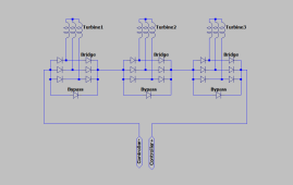
You can try to rectify the output of each wind turbine to DC right at the pole then wire all of that DC in series. And each rectified DC from each turbine gets its own bypass diode, just like series PV.

Here's an example with 3 turbines: WGsIxT4.pngAlso the bypass diode isn't really 100% needed because the bridge rectifier can also work as one, the advantage is that it lowers the voltage drop when a turbine is not producing.

You should also add a brake switch to each wind turbine just in case btw, you can use a double pole switch like this:
You would do two series sets, one for all the 48V turbines and one for all the 24V ones.
 
You can try to rectify the output of each wind turbine to DC right at the pole then wire all of that DC in series. And each rectified DC from each turbine gets its own bypass diode, just like series PV.

Here's an example with 3 turbines: View attachment 76843Also the bypass diode isn't really 100% needed because the bridge rectifier can also work as one, the advantage is that it lowers the voltage drop when a turbine is not producing.

You should also add a brake switch to each wind turbine just in case btw, you can use a double pole switch like this:
You would do two series sets, one for all the 48V turbines and one for all the 24V ones.

I have done a series of 6 exactly like you image, with an electrolytic capacitor of 5000uF for each of them in series and without the bypass diode as i was considering 3 of the diodes will bypass if that wind turbine is not spinning.

Problem is that 3 of them are always stalling never start to spin. As I disconnect their DC output from the series they they start to spin.
I have checked several times the capacitor connection and also checked 3-phase bridge rectifier and all of them are ok.

I will want to understand why this was not working. Stalling was happening also when there was no load on the entire series because load is applied only when voltage of the series is above 120V and mppt starts adding load.

Also I was noticing a voltage drop from 120V to 60V when circuit is closed by MPPT and this is probably because capacitors are not all at the same charged level so they can't equalize, this happens only when entire series is closed and than all capacitors will be equalized in voltage.

What might be the issue ?

You had the capacitor where the bypass diode would be on my diagram right? All 6 turbines are of the same voltage?

You made sure that you did not wire any of the capacitors backwards right?? Because that would explain the stalling.

Try an add the bypass diodes, because that way the bridge rectifier is not conducting at all when a turbine is stalled. And since this only seems to happen with only 3, I would test different combinations to make sure that it is not an issue with a specific turbine or rectifier or something is miswired.
You had the capacitor where the bypass diode would be on my diagram right? - yes, electrolytic capacitor, with correct polarity
All 6 turbines are of the same voltage? -> yes , all 48V
You made sure that you did not wire any of the capacitors backwards right?? Because that would explain the stalling. >> yes I checked several times
Try an add the bypass diodes, because that way the bridge rectifier is not conducting at all when a turbine is stalled. And since this only seems to happen with only 3, I would test different combinations to make sure that it is not an issue with a specific turbine or rectifier or something is miswired. >>>> yes, I will have to by separately single diode, probably you say that current will pass through a single diode insead of having to go through 2 in series from rectifier bridge.

I still can't explain this behavior. I have started to configure advanced controllers for each and add all of them in parallel, because I have noticed that if you add the same load in amps to all of them, the wind turbine that has highest RPM will continue to increase the RPM at the same load and as the MPPT increases the load as the voltage rises, the ones with highest RPM continue to increase and the ones with low RPM will have lower and lower RPM and this might be conclusive for me that it is not possible to have all of them in series without series side effects like too high rpm, magnets damaging, blades get broken...

I have controller with 5 point load that i will add one for each wind turbine and configure the points of load based on RPM and not voltage.

See all settings I have for the wind controller.
 

Attachments

  • rpm load controller.jpg
    rpm load controller.jpg
    136.5 KB · Views: 4
  • MAX-I2-WSII-05-1 MAX-I1-WSII-0.pdf
    991.4 KB · Views: 3
Why not take small 3 phase transformers and bring the voltage up to 240 volt 3 phase or higher if you dare.. then rectify each of them at the windmill or in the house .. now you can parallel them at high voltage DC . Use mppt if you feel it is efficient..
Or rewind the windmills for higher voltage.

Nice project and problem.

Can you send some links with price for one 3-phase transformer from 48V to 240V ? I will need to use 20 transformers (and also add transformer loss) and that might be more expensive than having the additional wires in parallel instead of series.
 
My own projects involve scrapyards, fleabay, university salvage.. if you go a pro route with this then it will cost a lot of money... No doubt salvage aluminum entrance wire will be the cheapest.

Good luck.
Johan
 
One more thing depending how the windmill is wired.. star or delta...you might be able to reconnect to star for higher voltage.
 
One more thing depending how the windmill is wired.. star or delta...you might be able to reconnect to star for higher voltage.

Hehe, already checked that and between 24V and 48 the factory only switch from delta to star and I am using 48V so I can't do that ...
 
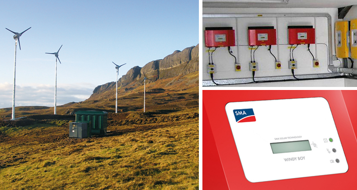
AC coupled wind turbines. Each gets its own GT inverter.
Those used to be available from SMA in the low kW range.


Could Enphase microinverters handle rectified AC from the turbines? Seems like the right voltage range. What would be needed for protection?
 
I am searching for a way to connect 20 wind turbines to 48V battery bank, we have 10 wind turbines of 48v and 10 of 24V both are 10A wind turbines.
I know I'm late to the party but I would suggest that before you go too far down this road why don't you install one turbine and see how it does at your site?
 
I do not think that is feasible. Especially at that distance I would much rather either just go solar or try to find a single really large turbine for sale locally. 20 turbines is 20x the amount of moving parts and 20x the maintenance.
I strongly object to the 'go solar' default. Wind ain't over until the fat lady sings
 
AC coupled wind turbines. Each gets its own GT inverter.
Those used to be available from SMA in the low kW range.


Could Enphase microinverters handle rectified AC from the turbines? Seems like the right voltage range. What would be needed for protection?
Rectified voltage is DC yes? Perhaps I missed something new
 
I found that zeroing in on the problem parts and ask on specialist fora could yield better results.
in this case a part might be 'how to combine multiple 3 phsse sources'
and if feadable deal with the rest later and/or elsewhere
 
Can you send some links with price for one 3-phase transformer from 48V to 240V ?
You can use three separate single phase 48v to 240v transformers, each rated for one third the total power.
These are standard stock items and readily available.
With the 240v secondaries connected in star, and rectified you will get 415v phase to phase ac and around 580 volts dc.

That should be enough surely.
 
Back
Top