diy solar

diy solar

EVE-280 cells should these be clamped tight or spaced for expansion?

...the specs on the silicone indicates they are 12 pounds per square foot...
I think you're looking at the spec for density: 12 lbs/cubic foot.
BTW, foam often has a spec. expressed in lbs. per SQUARE foot, but that is just the weight of a given thickness, e.g.: most carpet underlayment foam is upwards of 10-12 lbs. per square foot.
 
I think you're looking at the spec for density: 12 lbs/cubic foot.
BTW, foam often has a spec. expressed in lbs. per SQUARE foot, but that is just the weight of a given thickness, e.g.: most carpet underlayment foam is upwards of 10-12 lbs. per square foot.
4” of given material, compressed to 3” (25%) is standard rating…. (https://www.foambymail.com/blog/und...rength-and-applying-the-values-to-your-needs/) So how can we possibly convert that into required 3/8 foam specifications?
 
That's 25 percent compression from original thickness. Do the math.
That's 1/4" compressed to 3/16" (compressed by 1/16" or 1.587 mm)
Or sixteen 1/4" thick pieces (4" total) compressed to 3” total.
Or seven 1/4" thick pieces (1.75" total) compressed to 1.3125” total, e.g.: what you'd have with 8 cells together.
BUT the expected compression is about 0.5mm per cell, which is less than that.
So you probably want thinner foam or much stiffer foam than 12psi @ 25%
 
One thousand three hundred thirty pounds? WTH! I’m still confused about amounts of compression needed! EVE280 specifications show 300kgf (kilogram foot pound) 260 inch pounds or 21.7 foot pound is what they used. Please clarify. Thanks
For each row of cells you have you want 660 lbs of "force" If you have 2 rows of cells sharing a side plate then the total force that side plate is exerting is 1320 lbs.

If you look at the sketches below it could help your understanding.
Sorry not to get back to you sooner. Seems that this is a rather intractable problem. I have asked
a couple on engineering friends and they also are not sure which way it should be. The answer seems to be that if there is no deflection in the plate either way will work. If there is deflection then evenly distributing the pressures is probably the way to go. If there is more pressure on the middle of the plate and the plate deflects then over time there will be more pressure on those parts of the plate that are deflecting. One of the engineers is going to do a vector diagram to see how that looks..... I am waiting on that.

I have attached a couple of drawings for clarity:

A is simply one cell with four bolt/springs applying 660 pounds of force on the cell face
B is illustrating two cells and two plates side by side but not attached to each other
C is one plate covering two cells and having evenly weighted bolt/springs applying force
D is one plate covering two cells and having the combined force of the 4 bolt/springs in the
centre of A replaced with 2 bolt/springs
View attachment 78280


The next drawing is how I am trying to arrange a 48 volt series pack with 16 EVE 280 cells. There will be 4 cells wide by 4 deep, bolt/springs represented by the circles, not to scale. The weights on the bolt/springs to be determined.View attachment 78279
 
That's 25 percent compression from original thickness. Do the math.
That's 1/4" compressed to 3/16" (compressed by 1/16" or 1.587 mm)
Or sixteen 1/4" thick pieces (4" total) compressed to 3” total.
Or seven 1/4" thick pieces (1.75" total) compressed to 1.3125” total, e.g.: what you'd have with 8 cells together.
BUT the expected compression is about 0.5mm per cell, which is less than that.
So you probably want thinner foam or much stiffer foam than 12psi @ 25%
Okay let us start at point x. Say 4 cells with 3/16 (0.1875” or for argument sake say 4.5mm) foam. That’s 5 pieces total.

Now each cell expands.5mm per side, resulting in 1 mm “expansion pressure” between the cell’s upon the foam, and.5mm “expansion pressure “ against the aluminum bookends.

Let’s concentrate with the three center foams, and a 25% compression material . Therefore movement from 4.5 would result in 1.125mm.

However I believe one must include the starting pressure (cells bound) as well as the cells SOC.

On theory 4 cells at 50% SOC and torque at say 12psi with 3/16 foam of 25% compression should keep them under the 18psi damage range when fully charged.
Am I missing something?
 
...say 12psi with 3/16 foam of 25% compression should keep them under the 18psi damage range when fully charged.
Am I missing something?

The main thing you may be missing is knowing what the compression curve of any given material looks like.

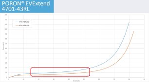
What you want is a foam (or very soft rubber) that maintains a fairly constant compression rate (psi) over a fairly useful range of compression (inches or mm), measured in percentage of original thickness that corresponds to the cell expansion of about 0.5mm (or whatever it actually is). That, and you want it to maintain as close to its original stiffness as possible over the years it will be in service.

As an example, let's say you have foam that is 4mm thick (uncompressed) and it is installed when the batteries are below 30% SOC & then compressed to say, 3mm thick (i.e.: compressed by 25% of original thickness), at which the specs say it exerts 9 psi pressure).
Then when each battery is fully charged, it expands by 0.5mm, and the foam will be compressed to 2.5mm thick (on average), which is compressed by 33% of original thickness, resulting in somewhat higher pressure. In most cases you will only find specs for 25% & 50% compression, but (for example) if the foam exerts 9psi at 25% compression and 15psi at 50% compression, you can be sure it will be a lot less than 15psi at 33% compression.

The other factor is compression set, which is how much of that initial spring pressure is eventually lost when the foam stays compressed a long time. The best foams for this application have long-term compression of less than 10%

This is why the Poron EV Extend was designed specifically for this purpose: it has a pretty flat pressure curve in this compression range
Untitled 1-29.jpg
and very low compression set.
rogerscorp.com/-/media/project/rogerscorp/documents/elastomeric-material-solutions/poron/english/data-sheets/poron--evextend-data-sheet.pdf

But other foams will work OK too.

...each cell expands 0.5mm per side, resulting in 1 mm “expansion pressure” between the cell’s upon the foam...
You'd only count this expansion (basically) once per cell, not twice as in your example above.
Another way of looking at it that each cell expands half of that 0.5mm (or whatever it actually is) in each direction, or 0.5mm total (hypothetically, I guess cells could be prone expanding asymmetrically.
 
Last edited:
The main thing you may be missing is knowing what the compression curve of any given material looks like.
What you want is a foam (or very soft rubber) that maintains a fairly constant compression rate (psi) over a fairly useful range of compression, measured in percentage of original thickness that corresponds to the cell expansion of about 0.5mm (or whatever it actually is).
As an example, if you have foam that is 4mm thick (uncompressed) and when the batteries are below 30% SOC, the foam separators are compressed to say, 3mm (25% of original thickness, at which the foam specs say they exert 9 psi pressure). You may not know

Then when each battery expands

This is why the Poron EV Extend was designed specifically for this purpose: it has a pretty flat pressure curve in this compression range


You'd only count this expansion (basically) ONCE per cell, not twice as in your example above. Or another way of looking at it that each cell expands half of that 0.5mm (or whatever it actually is) in each direction.
I thought EVE304 expanded 1mm (.05mm per side), when placed next to another cell , then each .05 movement upon each side of spacer comes into play. Therefore there’s.1mm of action on each spacer. I agree about using a different one, as the diffusion will be different depending upon thickness and starting compression. Is it generally understood that 12psi applied torque to each rod at 50%SOC ??
 
I thought EVE304 expanded 1mm (.05mm per side)...
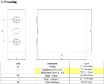
I don't know about EVE302 but this thread is about the 280s. The latest LF280K specs don't mention any different unclamped/clamped dimensions, but the specs from 2019 show 0.5mm increase in thickness between 30%SOC & 100%SOC, i.e.: 0.25mm per side or 0.5mm for two adjacent cells:
Untitled 1-29-1.jpg
If using cells rated to expand more than that, then of course adjust accordingly. The more the cells expand, the thicker the foam will have to be to keep the compression within the foam's 'sweet spot' above 25% but lower than 50%
 
Last edited:
I don't know about EVE302 but this thread is about the 280s. The latest LF280K specs don't mention any different unclamped/clamped dimensions.
But the specs from 2019 show 0.5mm increase in thickness between 30%SOC & 100%SOC, i.e.: 0.25mm per side or 0.5mm for two adjacent cells:

Okay My Bad. I agree about having stiff foam with constant deflection (impossible) Now, since the movement of .5mm increases pressure, and you selected a material that at 25% was 7psf (not 7psi as I would expect), how can one determine the increase delta change when expanded?
 
...you selected a material that at 25% was 7psf (not 7psi as I would expect)...
Nope

how can one determine the increase delta change when expanded?
Read this:
As an example, let's say you have foam that is 4mm thick (uncompressed) and it is installed when the batteries are below 30% SOC & then compressed to say, 3mm thick (i.e.: compressed by 25% of original thickness), at which the specs say it exerts 9 psi pressure). Then when each battery is fully charged, it expands by 0.5mm, and the foam will be compressed to 2.5mm thick (on average), which is compressed by 33% of original thickness, resulting in somewhat higher pressure. In most cases you will only find specs for 25% & 50% compression, but (for example) if the foam exerts 9psi at 25% compression and 15psi at 50% compression, you can be sure it will be a lot less than 15psi at 33% compression.

That's about it for me.
 
Thanks!!! but I’m guessing if I put together four or eight cells at 30%SOC with the 4mm/25% foam as indicated by you, and torque ALL my nuts on the compressing rods until the spacing between the cells are 3mm, then I theoretically should be good to go! Thanks hope I have it correct now ?
 
Just for clarification of those just joining: Yes, the thread was originally about the EVE 280 Ah cells. However, the EVE 304 Ah cells want basically the same treatment. The latest EVE 304 Ah specs that I found were from Version B, dated 2020-05-07, posted on this site several times or at

Compression is still specified at 300kgf. Based on the body dimensions, the compression still works out to right at 12 PSI.

Thickness is specified as 72.0±1mm at 40% SOC while under 300±20kgf.

Cycle Life is at least 3500 cycles when compressed and kept at 25 ±2 °C.
At 25 ±2 °C,the battery under 300kgf
fixture : charging the cell with charge
current 1.0C(A) and constant voltage
3.65V,0.05C cut off,rest for
Cycle Life at 25°C≥3500 cycles @1C/1C30min,discharge to 2.5V cut off with the
current of 1.0C(A),rest for 30min,and then
start the next cycle,end with the capacity
decrease to 80% of the initial capacity.The
number of cycles is defined as the cycle life
of the battery
 
Okay i’m thinking of putting three on one side three on the other side nuts and washers on both of them the question is i if I use springs how can I achieve the proper compression?
 
Putting a compressible mat between the cells sounds like a really good idea but once again I’m confused with your decision the specs on the silicone indicates they are 12 pounds per square foot it’s my understanding that most compression is at 12 psi (8-17 psi) any guidance on your choice may help. Thanks

I think you're confusing density with compress-ability...
  • Density: Ultra Soft: 12 lbs./cu. ft.; Extra Soft: 20 lbs./cu. ft.
  • Pressure to Compress 25%: Ultra Soft: 3 psi; Extra Soft: 7 psi
I chose that particular foam because it's compress-ability was close to Norseal but 1/3 the cost.
Norseal was discussed in this thread:


There are other types of foam to choose from, your choice...

 
Okay i’m thinking of putting three on one side three on the other side nuts and washers on both of them the question is i if I use springs how can I achieve the proper compression?
You measure the springs to make sure you understand how much to compress them for a given force, then you compress them that much.
 
Hello everyone.. I am new to this forum (and very thankful for it!) and up untill now have only been reading.

Now I may have something little to contribute aswell.

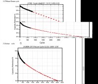
I just watched a video of "Off Grid Garage" about whether or not to put pressure on the cells and by his reaction to the graph I realized, the graph *could* lead to some false interpretation.

I just tried and put those graphs in the same scale. It now is much easier to consume and I think worth sharing.
They are much closer to each other up untill roughly 1500 cycles than what it looks like at first glance (when looking at the original graphs).
scaled.jpg
Sorry if this was already discussed before.
 
Since I helped derail this conversation, I suppose its fair that I rerail it. There have been many fragmented and scattered conversations on cell compression/fixture, some more current than this one, but since this is where I originally pointed out the relationship between fixture and cycle life in the EVE spec sheet, it seems as good a place as any to report some new-to-me information that I happened across while researching low temperature charging that may finally help explain and contextualize the 300kgf figure. I will also try to summarize and bring together the various bits and pieces of information scattered throughout a half dozen threads here (with references and links).

There are a pair of ongoing discussions on low temp charging going on here and here. I brought up a chart from a video by Ian George I had seen a few times a while back that has some useful info on low temp charging in the first few minutes. On this occasion I let it play through to the and had an 'aha moment' during the last slide where he discusses optimal pressure for pouch cells. Looking at the chart, I noticed it was 12 PSI, now most people are familiar with the 300kgf figure, but some may remember a while back we converted that figure to PSI, specifically..., 12 PSI. @BiduleOhm confirmed my calculations, and @Luthj came to the same conclusion independently in the Xuba thread. 300kgf = 661lbf = 2942N = 12psi spread across the broadside of an EVE cell. @ghostwriter66 is reaching out to EVE tonight, to try to get further clarification, we shall see. (we see: here and here

The video referenced earlier explicitly states not to focus on the specific numbers but to focus on the concepts and trends being illustrated, and I want to reiterate that advice. But I still can't help but notice that both reference 12psi. Sticking to the creators advice though, conceptually, both the relevant sections of EVE spec sheet, the e-mail response @Gazoo was able to get from an EVE rep, and the info in the video referenced above all seem to point to the same thing. Some amount of pressure is good for the life of the cells. This article posted by @Luthj alludes to the same conclusion, and is briefly touched on in this comment and this comment

In terms of why pressure is beneficial, I won't try to explain--watch the video, and read this comment--but the basic idea is that uniform pressure across the case is good for the internal 'jelly roll' or in the case of the video the pouch cells which lack external structure.


My theory, and this is speculative, of why its the large form factor aluminum cells that seem to be the ones most likely to explicitly recommend compression (EVE 280, Lishen 271) is that as cells get larger, and surface area increases, the exterior structures of the cells--particularly the broad sides--are increasingly in need of external structure/form. It is worth noting CALB cells also recommend "clamping" but do not elaborate beyond that.

Attached are the relevant sections of the EVE spec sheet, a screenshot of Gazoo's e-mail exchange with EVE, a screenshot from the referenced video, and an X-ray image of a 'jelly roll'

Here are some threads and posts on the topic:
EVE 280Ah LiFePO4
Xuba Megathread
CALB Grey Cell Compression Casing
EVE LF280 Charge Cutoff Voltage
Best Ways to compress Cells in Pack
EVE Cells Should these be Clamped Tight or Spaced for Expansion
...Some examples of compression
Hi Dzl,

What if I have two cells side by side and I have to compress 2 rows at the same time (16S in 2 row arrangement)
What force should I use then?

Thanks,

A
 
How can one mechanicaly achieve 12psi! I have not found an answer!!. Therefore I have decided to use liquid neoprene pads which have a compression ratio 25% to 75% which are rated at a psi of 7 to 15 respectively. The only thing I can figure is if I start at 30%SOC with a 4 mm separators and I tighten my binding rods until the pads are 3 mm each , then I have achieved my seven psi. Any thoughts? (Of course I will use a micrometer to check them after they are fully charged at proper temperature @ 90 SOC.)
 
Back
Top