diy solar

diy solar

Just a total noob building a 8S JBD BMS from Amy Wan

damon6sdl

New Member
Joined
Jan 19, 2022
Messages
22
Hi there!

This thread is the next step of this one, just so you know: https://diyjust-a-total-noob-willing-to-built-a-8s-from-amy-wan

I started with 8S for a 24V 280AH battery. This is paired with a 2000VA inverter and plugged through a MPPT 150/60.
300368183_2007610816294581_7303576004825902586_n.jpg

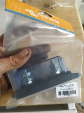
About the BMS, Amy offered JBD BMS 8S 100A.
300244200_3369635509961892_1992639556739034762_n.jpg

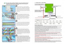
I built the box, did the cable management and so on. But now I'm stuck. Here is the data she shared with me
9F1592DA24EF8CC3978F60F84DFB5D73.jpg
So she told me the 2 B- have to be attached together and therefore plugged to the total minus of the battery
299836024_860981548207860_7480694646828761489_n.jpg
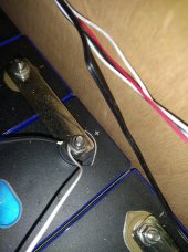
But then, if I understood everything right as a total noob, the 2 C- have to be plugged with the Minus electrode of the MPPT. But I have just no idea on how to plug all these together. It's way too big for a tin solder (I tried...). So this is my main question here: how am I supposed to do this?! Did someone face the same problem already? Is the configuration good?
299605957_773720500540802_7223443145399975502_n.jpg
Sorry for that one, never been a great photographer.

Thanks in advance for your help fellow experts !
 
The BMS wires being short, you need to extend them with a single cable
Before all, thanks for your answer. So if I got you right, the busbar will be used to extend the BMS wires? Because I have no idea how to extend the 2 C- wires... So that's a busbar with on one side the 2 BMS cables, and on the other side the MPPT cable? Thanks
 
Here is a suggest topology using busbars.

This one for the positive side

This one for the negative side

The attached text file is a textual representation of a system topology.
It looks confusing at first glance but the legend block describes all the bits and pieces.
The general idea is that all the system components are connected between the busbars.

If you have any questions just holler.
 

Attachments

  • damon6sdl.txt
    1.5 KB · Views: 10
For fine stranded wire into mechanical lugs I suggest ferrules.
The bms c- wires are 8 awg, confirm?
 
Before all, thanks for your answer. So if I got you right, the busbar will be used to extend the BMS wires? Because I have no idea how to extend the 2 C- wires... So that's a busbar with on one side the 2 BMS cables, and on the other side the MPPT cable? Thanks
The buss bars are for making all connections to the system. Unless you can mount the negative buss bar direct to the b- cables you would find convenient locations for both buss bars (keeping in mind your CC and inverter connections) and make up a single cable to extend the B- cables to the - buss bar. and another cable to go from the battery + to the + buss bar.
 
For fine stranded wire into mechanical lugs I suggest ferrules.
The bms c- wires are 8 awg, confirm?
I honestly have no clue !!

If you have any questions just holler.
Thank you, I'll check that with my friend and see how it goes !
The buss bars are for making all connections to the system. Unless you can mount the negative buss bar direct to the b- cables you would find convenient locations for both buss bars (keeping in mind your CC and inverter connections) and make up a single cable to extend the B- cables to the - buss bar. and another cable to go from the battery + to the + buss bar.
Thank you for informations !
 
I honestly have no clue !!
I can see now in your picture that the wires are 10 awg with insulation rated for 200C.
This table
Says that 10 awg wire with 200C insulation is good for 75 amps.
Since you have 2x for the battery side and 2x for the system side then you are good for 150 amps fault current.
150 amps * .8 fuse headroom = 120 amps service current.

Since the wire is fine strand you should put a ferrule on the wire before terminating on the negative busbar I linked previously.

Suggest that every time that hit a word or concept that you don't understand to use google.
 
The black wires go to the battery negative terminal..
The blue wires go to the system negative busbar.

Be darn careful working on the battery terminals and always were eye protection.
 
The black wires go to the battery negative terminal..
The blue wires go to the system negative busbar.

Be darn careful working on the battery terminals and always were eye protection.
If I m no wrong it's the opposite, the blue wires to the battery negative terminal while the black wires go to the MPPT module. And yes I did google 8 AWG so I knew it was a kind of cable, but had no clue if mine was 8 or 10. Thanks for your help
 
If I m no wrong it's the opposite, the blue wires to the battery negative terminal while the black wires go to the MPPT module. And yes I did google 8 AWG so I knew it was a kind of cable, but had no clue if mine was 8 or 10. Thanks for your help
It just goes to show, you can't always trust info you get on the internet.
 
If I m no wrong it's the opposite, the blue wires to the battery negative terminal while the black wires go to the MPPT module. And yes I did google 8 AWG so I knew it was a kind of cable, but had no clue if mine was 8 or 10. Thanks for your help
Sorry, made a typo or a thinko.
Not sure which.
 
So guys this is basicaly what I have in mind with the infos you gave me. Would it do the job you think?? Thanks in advance for your answers @John Frum @littleharbor2
 

Attachments

  • 308084127_788536305849991_2077355843261970046_n.jpg
    308084127_788536305849991_2077355843261970046_n.jpg
    106.8 KB · Views: 12
For fine stranded wire into mechanical lugs I suggest ferrules.
The bms c- wires are 8 awg, confirm?
Hi again, sorry for bothering you...

An other issue I have here is due to the very thin BMS cables: these are 24 AWG. So i'm still considering if I should weld them to the battery units, nor if I should keep trying to find some pods that are small enough to meet them on one side, but large enough to go through the battery units top (5mm)... Any tips on this? Thanks in advance!!
 

Attachments

  • 310935038_654948282698173_251336395723328563_n.jpg
    310935038_654948282698173_251336395723328563_n.jpg
    200.2 KB · Views: 8
Hi again, sorry for bothering you...

An other issue I have here is due to the very thin BMS cables: these are 24 AWG. So i'm still considering if I should weld them to the battery units, nor if I should keep trying to find some pods that are small enough to meet them on one side, but large enough to go through the battery units top (5mm)... Any tips on this? Thanks in advance!!
What? You want all leads to have terminals crimped on a heat shrunk.
I would drill and tap holes in your current buss bars to install the balance leads instead of stacking on the battery terminal.
It sure looks like you just have the wire tucked under the nut and tightened down, this is not good.
 
Back
Top