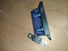
Also still wondering: why are these 2 things looking so different for doing (as far as i understood) the same thing, which is connecting cables?This one for the positive side
This one for the negative sideMRBF Surface Mount Fuse Block - Common Source - Blue Sea Systems
Easily and economically satisfies ABYC 7 circuit protection rule by mounting on a 3/8 battery post, battery switch or bus bar.www.bluesea.com


You are using an out of date browser. It may not display this or other websites correctly.
You should upgrade or use an alternative browser.
You should upgrade or use an alternative browser.
Just a total noob building a 8S JBD BMS from Amy Wan
- Thread starter damon6sdl
- Start date
John Frum
Tell me your problems
- Joined
- Nov 30, 2019
- Messages
- 15,233
The positive side is fusable.Also still wondering: why are these 2 things looking so different for doing (as far as i understood) the same thing, which is connecting cables?
The negative side is a old style busbar.
Yes, I did that just "to see" but that is def not the way I want to do it. That's my question tho, how to do it clean :D @Supervstech gave an answer I can understand and even feel easy to do. And if I understand yours, welding is the worse option to consideer. I understand the idea of making holes in the busbars, but then I miss smthg: since those busbar are connecting units together, where shall I do a new hole to make sure the contact is done specificaly with the positive pole?What? You want all leads to have terminals crimped on a heat shrunk.
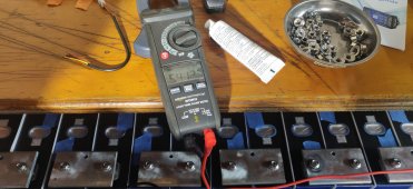
I would drill and tap holes in your current buss bars to install the balance leads instead of stacking on the battery terminal.
It sure looks like you just have the wire tucked under the nut and tightened down, this is not good.
So both with fusable units as the Victron one I posted would do the job right?The positive side is fusable.
The negative side is a old style busbar.
John Frum
Tell me your problems
- Joined
- Nov 30, 2019
- Messages
- 15,233
The victron lynx series has both a fusable positive busbar and a non fusable negative busbar.So both with fusable units as the Victron one I posted would do the job right?
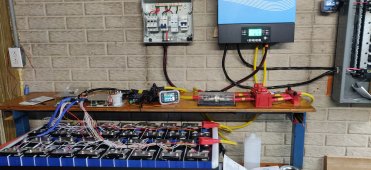
This is what I boughtThe victron lynx series has both a fusable positive busbar and a non fusable negative busbar.
Attachments
42OhmsPA
What's in a title?
Photos are worth thousands of words.Yes, I did that just "to see" but that is def not the way I want to do it. That's my question tho, how to do it clean :D @Supervstech gave an answer I can understand and even feel easy to do. And if I understand yours, welding is the worse option to consideer. I understand the idea of making holes in the busbars, but then I miss smthg: since those busbar are connecting units together, where shall I do a new hole to make sure the contact is done specificaly with the positive pole?
Attachments
John Frum
Tell me your problems
- Joined
- Nov 30, 2019
- Messages
- 15,233
For which circuit?This is what I bought
What is the ampacity rating of the fuse?
What is the awg of the wire?
Fuse is 175A. Calculated this way: My inverter is victron Phoenix 2000VA, 4000w crest. So 4kw. So 4/24 = 0,166For which circuit?
What is the ampacity rating of the fuse?
What is the awg of the wire?
About the cables: on one side are the 2 C- cables. They both are 10 AWG. Other side is a 4 AWG cable reaching the Minus electrode of the MPPT
I see! But (I might be wrong: remember the topic, I'm a total noob) if I m no wrong, it works with you because your units are paired in parallel, so one busbar is pairing both + of units. While for me it's all in series so I have no full positive busbars. So I guess if I make a hole in the middle of the busbar it wont work at all. Did I win?Photos are worth thousands of words.
42OhmsPA
What's in a title?
No individual cells are paralleled, there are 2 16s/48v packs paralleled at the current connected bus bars.I see! But (I might be wrong: remember the topic, I'm a total noob) if I m no wrong, it works with you because your units are paired in parallel, so one busbar is pairing both + of units. While for me it's all in series so I have no full positive busbars. So I guess if I make a hole in the middle of the busbar it wont work at all. Did I win?
Ok so u just make a hole in the middle of a busbar connecting the - and + of units? I'm impressed! Again I know nothing, but it sounds so special as they insist to plug these cables to positivesNo individual cells are paralleled, there are 2 16s/48v packs paralleled at the current connected bus bars.
Yes, but you still connecting to the positives even in the middle of the busbars. Think about which way the current to the BMS runs irrespective of whether your + of one cell is connected to the - of the next cell.Ok so u just make a hole in the middle of a busbar connecting the - and + of units? I'm impressed! Again I know nothing, but it sounds so special as they insist to plug these cables to positives
Just remember to take your busbars off to drill them as we don't want to see you in the ‘Up in Smoke‘ forum

Ahahahah that could have happened for sureYes, but you still connecting to the positives even in the middle of the busbars. Think about which way the current to the BMS runs irrespective of whether your + of one cell is connected to the - of the next cell.
Just remember to take your busbars off to drill them as we don't want to see you in the ‘Up in Smoke‘ forum
Thanks mate!Now that I understood the fact the whole busbar is actually like the positive pole, I still am wondering how you get those really tiny cables to fit into this hole? I see you used some sort of nut but how is the cable attached? Thanks a lot for your ideas btwI would drill and tap holes in your current buss bars to install the balance leads instead of stacking on the battery terminal.
42OhmsPA
What's in a title?
Ring terminals are crimped on the end of the balance lead. The bolt goes through the ring terminal to fasten to the buss bar hole you drill and tap.Now that I understood the fact the whole busbar is actually like the positive pole, I still am wondering how you get those really tiny cables to fit into this hole? I see you used some sort of nut but how is the cable attached? Thanks a lot for your ideas btw
Is it fine u think? Thanks in advanceFor which circuit?
What is the ampacity rating of the fuse?
What is the awg of the wire?
But then... What's the difference with just using the "bolt" that is already on the battery unit? Beside that you can choose a tinyer one? And how did you manage to crimp the ring terminals on such small cables? As mentionned yesterday, by stripping and folding them?Ring terminals are crimped on the end of the balance lead. The bolt goes through the ring terminal to fasten to the buss bar hole you drill and tap.
42OhmsPA
What's in a title?
Yes, stripped and folded.But then... What's the difference with just using the "bolt" that is already on the battery unit? Beside that you can choose a tinyer one? And how did you manage to crimp the ring terminals on such small cables? As mentionned yesterday, by stripping and folding them?
You get a better connection from the cell terminal to bus bar without the additional ring terminal.
You need ring terminals in the size that either fit your terminal bolts or the bolts on the busbar like these.But then... What's the difference with just using the "bolt" that is already on the battery unit? Beside that you can choose a tinyer one? And how did you manage to crimp the ring terminals on such small cables? As mentionned yesterday, by stripping and folding them?
https://www.cabac.com.au/p/electrical-power-connectivity/terminals/pre-insulated-terminals/rt1-25-6
and a crimper like this.
https://www.jaycar.com.au/5-way-cri...MIzNnWvr_b-gIV-IJLBR2eWAnPEAQYAiABEgIihPD_BwE
Similar threads
- Replies
- 73
- Views
- 4K
- Replies
- 24
- Views
- 1K
- Replies
- 3
- Views
- 294
- Replies
- 2
- Views
- 748
- Replies
- 10
- Views
- 789