diy solar

diy solar

First Time Battery Build Can Someone Help out?

Sunsetsolar

New Member
Joined
Apr 16, 2022
Messages
19
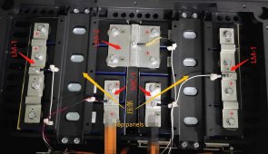
I have a kit from Seplos and they sent me the battery config its suppose to be 4s2p but if I load the batteries as in step six then place the bus-bars as in step seven I think I will have a big bang! And in step seven I see that the serial bar codes do not line up as the way the step six shows the batteries installed..

Can anyone take a look before I smoke this..
I called the vendor for tech support but No reply so I thought I might pass it by you guys...

This is a first time post so if its in the wrong format or location let me know and delete it and i'll try to set it up right..
Thanks!
 

Attachments

  • MERA 12V270AH Assembling Guide(3).pdf
    221.3 KB · Views: 25
You have a good eye, nice catch. You are correct, the assembly instructions are dangerously incorrect the cell orientation in the first case appears to be perhaps an 8S configuration while the bus bars are designed for the 4S2P configuration.
Are the bus bars in the kit exactly as shown in the pic?
 
yes the bus-bars are exactly the same looks like the battery will eat itself with the first step install!
 
Also in the 7th step if you look at the serial identifier codes they are mismatched from that of step 6..doh.
 
yes the bus-bars are exactly the same
Based on the color of the terminal insulators that are visible under bus bar LM-2, Brown on left & Black on right, are you comfortable assembling the battery in the proper 4S2P configuration working out from LM-2 and logically identifying the other cells orientation from that location?
 
That was my plan as I can see the orientation...
I will post a picture when done but I am waiting on eva foam they forgot to send but after I get that i will populate and post a picture for the forum to see and give me a blessing :)
Hopefully!
 
I will also upload a diagram of my thinking but need a little bit of time to set that up...
 
8 cells total
four sets of two 3.2v cells (in parallel)
those are then placed in series to give 12.8v
See attached picture...
 

Attachments

  • Revised layout.jpg
    Revised layout.jpg
    319.6 KB · Views: 18
Yes, that looks good. It always drives me crazy how the positive terminal on the cell is Black, I usually stick a small piece of red electrical phase tape next to the positive terminals on all the cells when I'm working with them just so I don't make a mistake if distracted or having an off day. The funny thing is most of the BMS and active cell balancing products from China do conform to the traditional Red wire is Pos & Black wire is Neg convention.
 
I know that's why I go slow because there is a lot of energy involved here it can melt a wrench....
I am just frustrated with their idea of tech support three requests and the same document sent all three times..
Ahh well I think I have got it just paranoid loll!
 
Final update...Got it working my diagram was correct but I could not get the BMS to turn on by pressing the on switch..
(Zero volts on output terminal)
What i found is you need the unit turned on and use a power supply to inject a charging current and that boots the BMS for the first time ...
After that it works great!
 

Attachments

  • IMG_20221113_065848.jpg
    IMG_20221113_065848.jpg
    167 KB · Views: 5
  • IMG_20221113_065854.jpg
    IMG_20221113_065854.jpg
    131.1 KB · Views: 5

diy solar

diy solar
Back
Top