You are using an out of date browser. It may not display this or other websites correctly.
You should upgrade or use an alternative browser.
You should upgrade or use an alternative browser.
Feedback of 12V van system plan
- Thread starter EnsignR
- Start date
FilterGuy
Solar Engineering Consultant - EG4 and Consumers
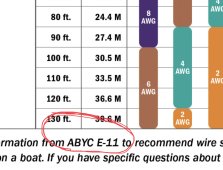
It comes from the American Boat & Yacht Council (ABYC) standard for marine wiring. You will notice that it is a bit less conservative than the NEC. That is why I will often go up one size for selecting wire size.Where is this table from? NFPA? MTW wire?
EnsignR
New Member
- Joined
- Sep 25, 2022
- Messages
- 19
Can you find & post the “Performance Specifications” for your already have 3 AGMs.
| Battery Chemistry | AGM Valve Regulated Lead Acid (VRLA) |
| Lead Calcium Grid Purity | 99.7% |
| Nominal Voltage | 12V |
| Nominal Capacity (C20 to 1.75V/cell) | 98Ah |
| Cycles at 30% Depth of Discharge: | ~1500 |
| Design Life on permanent float charge @ 25°C | Up to 10 Years (80% capacity retained) |
| Charge Voltage @ 25°C | 14.1~14.4V (-4mV / °C / cell) |
| Float Charge Voltage @ 25°C | 13.5~13.8V (-3mV / °C / cell) |
| Recommended max Charge Current | 22.5A |
| Internal Resistance: | ~6.5 mΩ (Fully charged) |
| Maximum Discharge Current (5 Seconds): | 900A |
| Self Discharge Rate | ≤3% per month |
| Operating Temperature – Discharging | -20°C to +50°C |
| Operating Temperature – Charging | -10°C to +40°C |
| Operating Temperature – Storage | -20°C to +40°C |
| Terminals | M8 Threaded with colour-coded Sealed Epoxy Blocks |
| Max Terminal Torque | 5.5Nm (±5%) |
| Hardware included | 2x M8 bolts 2x flat washers 2x spring washers |
| Case Material | ABS |
| Handle | Removable Polyester rope with plastic reinforcement |
| Dimensions(mm): | 307mm(L) x 169mm(W) x 215mm(H) |
| Weight(kg): | 24.5kg |
nb. I'll only be using the 2 brand new ones in the rebuild (probably).
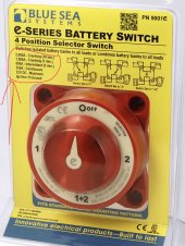
Here is an idea you might consider ,,, this is concept for you & I have not placed the fuses that would be required ,,, but a Blue Sea 4 Way Switch & eliminate your 2nd set of pos & neg bus;
Yes. I have considered installing a 2-way switch somewhat like you suggested so as to be able to charge the batteries both when the loads are either connected or entirely disconnected from the batteries. The problem being I haven't found one with a high enough current rating as yet; I really don't want to spend all the money up-sizing the wiring only to have the weak point be a single switch.
Indeed. Thanks.it is the idea that counts
EnsignR
New Member
- Joined
- Sep 25, 2022
- Messages
- 19
Thanks. I've made a copy to do later.Here is a spreadsheet
Yes I know... and it really is true. It chews power; 180W I believe. We tried it once for about 30 minutes just to see (before I knew it was 15A). In the design I put in a relay so it can only use 12V when there is power coming from the tow vehicle's alternator (which in turn would also be powering the DC-DC charger and thus supplying power to the whole system)I see you have a 3 way fridge. These don’t work well on solar/battery, they use too much electrical power. They are designed to run primarily on gas with AC when on unlimited shore power and 12V for when driving
RV8R
Solar Enthusiast
Yes. I have considered installing a 2-way switch somewhat like you suggested so as to be able to charge the batteries both when the loads are either connected or entirely disconnected from the batteries. The problem being I haven't found one with a high enough current rating as yet; I really don't want to spend all the money up-sizing the wiring only to have the weak point be a single switch.
Indeed. Thanks.
So the 4 Position “Blue Sea” Switch I posted earlier can take;
2,000 amps for 10 seconds
1,000 amps for 60 seconds
600 amps for 5 minutes
350 amps for “Ever” Or Continuous
It will be fine for your application. ?
RV8R
Solar Enthusiast
@EnsignR
Thanks for posting your battery specs;
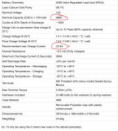
So the C20 capacity is listed @ 98 Ahrs
Max Charge is “Recommended“ @ 22.5 amps
The Max Discharge (not 5 seconds) is not listed, so unless specified I am going to guess @ 30 amps.
I think your biggest draw will be your 1500W Inverter & that will take about 150amps. You are planning on installing the 2 new batteries only. If that is the case & my 30amp per battery is a correct guess then you will have 60 amps available & need 150 amps. You can see, this is not going to work for the inverter.
I have not yet installed my inverter into my 12vdc systems. One of the reasons why is I think Inverters are a big deal for 12vdc batteries. If I was going to incorporate my inverter, I would be looking @ Lithiums & probably 4 x 100 amps 400amps capable.
In Short; I do not believe your batteries “will make the grade”.
So Pause that comment for a minute & let me tell you what I think “The Achille Heal” is in your system ,,, It is IMO “How Are You Gonna Charge Your Batteries”?
In that;
1) Shore Power ,,, no problem
2) Alternator Charging ,,, You might have a “distance” problem
3) Solar ,,, Sun dependent & I do not think you intend to hang out in Arizona ,,, might not be able to keep up.
I will throw this out for you. I once had a fellow Van DIYer “worry” about the 12vdc energy required for his water pump. Included it in his load chart for 45mins a day & 5 days use ,,, I told him to not even worry about the pump ,,, he was perplexed ,,, I asked “how many gallons do you carry on board” ,,, 30 he said ,,, & the pump? ,,, rated @ 3 gals per minute ,,, I replied your load chart has 45 minutes per day @ 5 days = 225 minutes total & then I said convert your fresh water tank into minutes of supply until empty ,,, he did the math ,,, it is 10 minutes at the rated flow.
I found out early the Van resource we conserve the most is the fresh water.
Back to your batteries;
The C20 capacity rating is 98 Ahrs ,,, what that means is if you drained your battery from 100% SOC “State Of Charge” to 0% in 20 hours you would get 98Ahrs total ,,, divide that by 20 hours = or 4.9amps for 20 hours. That is C20
Typically Lithiums (@ least in SOKs) are dischargeable @ C1 & have a C1 spec ,,, in SOKs for example ,,, the 100Ahr SOKs will give you 100amps for 1 hour.
This is why if I had a 12vdc Inverter, I am probably going with Lithiums. If one did want AGMs then IMO they should be expensive & great quality/performance & lots of them in Parallel.
Thanks for posting your battery specs;

So the C20 capacity is listed @ 98 Ahrs
Max Charge is “Recommended“ @ 22.5 amps
The Max Discharge (not 5 seconds) is not listed, so unless specified I am going to guess @ 30 amps.
I think your biggest draw will be your 1500W Inverter & that will take about 150amps. You are planning on installing the 2 new batteries only. If that is the case & my 30amp per battery is a correct guess then you will have 60 amps available & need 150 amps. You can see, this is not going to work for the inverter.
I have not yet installed my inverter into my 12vdc systems. One of the reasons why is I think Inverters are a big deal for 12vdc batteries. If I was going to incorporate my inverter, I would be looking @ Lithiums & probably 4 x 100 amps 400amps capable.
In Short; I do not believe your batteries “will make the grade”.
So Pause that comment for a minute & let me tell you what I think “The Achille Heal” is in your system ,,, It is IMO “How Are You Gonna Charge Your Batteries”?
In that;
1) Shore Power ,,, no problem
2) Alternator Charging ,,, You might have a “distance” problem
3) Solar ,,, Sun dependent & I do not think you intend to hang out in Arizona ,,, might not be able to keep up.
I will throw this out for you. I once had a fellow Van DIYer “worry” about the 12vdc energy required for his water pump. Included it in his load chart for 45mins a day & 5 days use ,,, I told him to not even worry about the pump ,,, he was perplexed ,,, I asked “how many gallons do you carry on board” ,,, 30 he said ,,, & the pump? ,,, rated @ 3 gals per minute ,,, I replied your load chart has 45 minutes per day @ 5 days = 225 minutes total & then I said convert your fresh water tank into minutes of supply until empty ,,, he did the math ,,, it is 10 minutes at the rated flow.
I found out early the Van resource we conserve the most is the fresh water.
Back to your batteries;
The C20 capacity rating is 98 Ahrs ,,, what that means is if you drained your battery from 100% SOC “State Of Charge” to 0% in 20 hours you would get 98Ahrs total ,,, divide that by 20 hours = or 4.9amps for 20 hours. That is C20
Typically Lithiums (@ least in SOKs) are dischargeable @ C1 & have a C1 spec ,,, in SOKs for example ,,, the 100Ahr SOKs will give you 100amps for 1 hour.
This is why if I had a 12vdc Inverter, I am probably going with Lithiums. If one did want AGMs then IMO they should be expensive & great quality/performance & lots of them in Parallel.
Last edited:
RV8R
Solar Enthusiast
I look at your diagram on your 1st post & the loads all look like 12vdc loads & nithing that major. However, without you making a load chart I am really just guessing.
What are your needs for an Inverter?
If you do make up a Load Chart, it would be best to split it up between 12vdc & inverter loads.
All the inverters I am aware of have a “standby load”. That is if they are turned on, they are draining your batteries down.
What are your needs for an Inverter?
If you do make up a Load Chart, it would be best to split it up between 12vdc & inverter loads.
All the inverters I am aware of have a “standby load”. That is if they are turned on, they are draining your batteries down.
RV8R
Solar Enthusiast
Regarding Battery Performance Specs;
Here is part of the battery specs I posted on my Rolls Batteries;
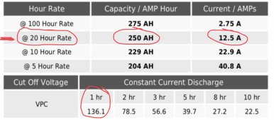
The “C20“ Capacity is 250Ahrs
Note the “C1” is 136.1Ahrs (by the way, this would probably pooch my AGMs)
I am posting this as for FLA & AGM batteries the capacity is greatly defendant upon the time frame ,,, not so much with “C1” rated Lithiums & that is why Lithiums are great for Inverters.
Here is part of the battery specs I posted on my Rolls Batteries;

The “C20“ Capacity is 250Ahrs
Note the “C1” is 136.1Ahrs (by the way, this would probably pooch my AGMs)
I am posting this as for FLA & AGM batteries the capacity is greatly defendant upon the time frame ,,, not so much with “C1” rated Lithiums & that is why Lithiums are great for Inverters.
EnsignR
New Member
- Joined
- Sep 25, 2022
- Messages
- 19
Indeed. I'd want something at least 250A continuous. However, it's also AU$80! ?So the 4 Position “Blue Sea” Switch I posted earlier can take;
2,000 amps for 10 seconds
1,000 amps for 60 seconds
600 amps for 5 minutes
350 amps for “Ever” Or Continuous
It will be fine for your application.
The manufacturer actually sells a kit with the same inverter, same MPPT and solar "blanket" and a single 98Ahr battery.I think your biggest draw will be your 1500W Inverter & that will take about 150amps. You are planning on installing the 2 new batteries only. If that is the case & my 30amp per battery is a correct guess then you will have 60 amps available & need 150 amps. You can see, this is not going to work for the inverter.
I'm not intending to have the inverter powered all the time - they also sell a remote switch (connected via RJ45) - to turn it on and off for that purpose. We'd only really be using it intermittently.
I have powered if off the current single battery just to test it wasn't DOA when it arrived and it worked; though admittedly I didn't power it for long.
Oh. I've no doubt that they're completely shit. All of their stuff is; it's all the same brand of cheap junk..... this is the part where I point out I wasn't the one who actually bought any of this stuff, and if it were up to me I certainly wouldn't have.In Short; I do not believe your batteries “will make the grade”.
For those in .au all I'd have to say is Kings and they'd probably understand.
My aim is to build something that will allow some decent replacements just to slot in when the original junk inevitably fails.
TBH I was quite surprised that I was able to dig up the amount of specs I did on the batteries. Their manuals are a disgrace and you basically have to guess how to get things working.
It's a very long and wet drive to get to Arizona from here.I do not think you intend to hang out in Arizona
This is the first time I've ever heard about C-rating. ?The C20 capacity rating is 98 Ahrs ,,, what that means is if you drained your battery from 100% SOC “State Of Charge” to 0% in 20 hours you would get 98Ahrs total ,,, divide that by 20 hours = or 4.9amps for 20 hours. That is C20
For anyone else reading this thread I found this page useful getting my head around it.
So far as these batteries not being enough to power the inverter (for long at least) then so be it. Personally I'm not really fussed as it would just be used for what I consider luxuries whilst boondocking. It was actually bought by that special someone to charge a laptop (I bought a Raspberry Pi instead) and to run a heater which is completely laughable IMO. So as long as it works intermittently to perhaps run a small microwave then I personally don't care and everything I care about will be 12V and I'll be able to say "I told you so". ?
My single main concern is building something that's safe enough so the system/wires are correctly sized so something catastrophic like a fire doesn't happen.
Last edited:
EnsignR
New Member
- Joined
- Sep 25, 2022
- Messages
- 19
Ha ha. Thanks. I did it using Google Drawings. Mind you it took me ages, mainly due to procrastination and a lot of unnecessary fiddling with hidden shapes to allow me to move things around and allowing the curved connector lines wires to move on their own.What did you use to create your diagram? That is amazing. I was about to post something and I am embarassed to post it now
Perhaps I should start a paid service creating designs on the Googles?
RV8R
Solar Enthusiast
Hi @EnsignR
I am in Canada, so there could be some differences in our equipment that I am unaware of.
If you post your battery Brand & Model, I will attempt to look up the performance specs for you if you want. When considering inverter use from a 12vdc battery bank there are 2 main things to consider & they both come from W=VA watts = volts x amps;
Current Needed; 1500W inverter / 12volts = 125amps (but rule of thumb is take the watts & drop a zero ,,, So 1500 watts = 150 amps). Due to inverter efficiency, blaa, blaa, blaa
For how long you can run the 1500W inverter you look at the battery bank energy storage, & with FLA & AGMs as you have now learned the batteries are typically rated capacity @ C20. Most decent Lithiums have a C1 ,,, So if they are 100Ahr you get 100amps for 1hour. Apparently my Rolls C20 250Ahr will give me a C1 of 136.1Ahr (I would have to dive into that part of the spec & I am skeptical ,,, nor is this a good way to treat AGMs IMO for longevity).
In Your Case; You have a 1500W Inverter ,,, but you intend on limiting the power (& energy), use of it to a much smaller “draw”. Take a look at the devices/appliances you will be running off your inverter & that with a multiplier (if unknown I would use 25%) for efficiency etc will get you what the Inverter theoretically will pull out if your battery bank. Example, 400W device multiply by 1.25 = 500W ,,, 500W divide by 12 volts = 42 amps. Then if your batteries provide 30 amps each 30 x 2 = 60 amps available then you are good ?. There of course is way more to it, but that is the basic.
Yes the Big Red 4 Position Switch is $65 CAN here (I have purchased 3 of them in a short time). I watched a video by “Will”,,, I think it was about SOKs. He repeated stated he is tired of hearing from people who buy cheap stuff & then complain to him that is isn’t working out well. For my 12vdc systems, I buy “Marine Grade” wire & component. It costs more. I do not design systems to 100% capacity & it costs more ( that is my designs are conservative ). I design systems for the easy cost effective possibility of future expansion, & guess what ,,, it costs more.
So goes my Design Philosophy, & my way ain’t everybody’s cup-O-tea. Guess what ,,, I rarely have system failures.
If you want my help designing your system, I can assist you with my ideas, the caveat is my ideas come with in engineering terms are a FOS, “Factor Of Safety“ & consideration of possible future alterations ,,, example increasing wire size. I am not trying to spend your money, but provide suggestions so it will work hopefully with few problems. This is why I am suggesting you perform a “Load Chart”. Because obviously ,,, I do not even know where you are on the “map” or electrical needs ?.
closing note; In “Vanlife”, many DIYers talk about “Building”, yet most of their questions are about “Design” ?. I write about this a lot, because IMO they are missing the understanding of the DIYer “Design / Build” process. I will put it in these terms ,,, The Building is the Easy part.
Last edited:
MisterSandals
Participation Medalist
I don't mind fudge factors, but i usually like to know what's behind the curtain.Take a look at the devices/appliances you will be running off your inverter & that with a multiplier (if unknown I would use 25%) for efficiency etc will get you what the Inverter theoretically will pull out if your battery bank.
What I've learned on this forum is that to quantify this fudge factor, folks also look at the cutoff voltage of the inverter. Many 12V inverters cutoff at 10V so...
1500W / .85 efficiency / 10V = 176A
Obviously if your inverter has a different efficiency or cutoff voltage, those numbers should be used.
Similarly:
400W / .85 / 10V = 47A (pretty similar to your results)Example, 400W device multiply by 1.25 = 500W ,,, 500W divide by 12 volts = 42 amps.
ianganderton
Auckland, NZ
As typically the highest wattage draw in a system inverters that have programmable cut off points are invaluable for preventing undue stress on the various components.Many 12V inverters cutoff at 10V so...
I’ve set mine to cut off at the top of my battery’s discharge curve knee. This will prevent extreme discharge stress on the battery and the higher amps in the cables caused by low voltage. It doesn’t make much in any real world difference to available battery capacity either. 5 to 10% max ?
MisterSandals
Participation Medalist
I've never owned an inverter that can be configured. It will be high on my list next time. Which inverter do you have?I’ve set mine to cut off at the top of my battery’s discharge curve knee.
RV8R
Solar Enthusiast
I don't mind fudge factors, but i usually like to know what's behind the curtain.
What I've learned on this forum is that to quantify this fudge factor, folks also look at the cutoff voltage of the inverter. Many 12V inverters cutoff at 10V so...
1500W / .85 efficiency / 10V = 176A
Obviously if your inverter has a different efficiency or cutoff voltage, those numbers should be used.
Similarly:
400W / .85 / 10V = 47A (pretty similar to your results)
Yup, I much prefer “Engineering” & agreed design parameters also. I like to see “The Math” behind ”The Curtain” ?.
Problem “here” is lack of performance specifications to properly design a system. The OP needs to find them & post them along with the ”Load Chart” & I suppose the “intended use” ,,, or all we are doing is chasing “Unicorns” with general “Fudge Factor Design” guesses of what may be.
But ,,, at least now he is educated a bit on battery “C” capacity ratings (Which is pretty important for inverter design).
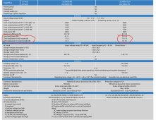
We have not even gotten to “Standby” or “Idle” or “Search” mode energy consumption. Here is the performance specs on my Victron 12 | 3000 | 120 that I purchased in 2018 & have never installed;
Last edited:
Lsversaw
New Member
RV8R, FilterGuy, and others who have provided thorough, detailed responses: Thank You! I’ve been following along and have learned a lot from this thread.
Similar threads
- Replies
- 4
- Views
- 209
- Replies
- 10
- Views
- 336


