diy solar

diy solar

My adventures building a DIY Mn/Fe flow battery

According to this, it's $8k for 11 kWh. Not sure where you can buy them, but supposedly they're available. Might try the source: https://redflow.com/.
Since this is Australia, importing to the EU would increase the price by 30% at least. They would need to drop the price further to compete with LiFePO4 server batteries.

It is very cool though.
 
I was just thinking that, they must have fixed the dendritisation (that should be a word :)) and I'm glad for them. The $8k is more than 5 years ago, so not sure what the real cost is today, but with VAT like Daniel mentioned, I estimate the cost for one ZBM3 to be around $11-13k, which for a commercial 10kWh battery with a cycle life at or better than 10 years, isn't too bad. But too bad doesn't mean its not an expensive system. We forge the BMS which RedFlow offer, that one is, I am sure, a few thousand as well. A multi 10kWh system will quickly be very expensive ...

Lets give the Mn/Fe battery a proper full size chance first :)
 
My objective is not to create something that can rival a product that took millions of dollars, dozens of people and a decade for a company to develop - that would be very naïve.

My objective is to provide a solution that could be viable to explore and use for people who want to DIY some solution that will not involve extremely acidic/basic solutions or dangerous or hard to find chemicals. I do not intend to create any product for sale, but only a base of knowledge that me and others can use. As currently we have no rechargeable DIY solution for storage that can provide something in the >10Wh/L range that people could realistically build.
 
Lets cross the BMS river once you know the operational points :)

- Edit -
Saying that, there is an Open Source BMS system for flow battery's.

"The architecture of foxBMS is the result of more than 15 years of development in innovative hardware and software solutions for rechargeable battery systems, redox-flow battery systems, and fuel-cell systems at Fraunhofer IISB in Erlangen (Germany). Consequently, we use the hardware and software building blocks as battery management system at Fraunhofer IISB in all of our research and development projects (Technical Specifications). Further, our self-developed 100kWh stationary lithium-ion battery system to store electric energy generated by photovoltaic panels and our TÜV road homologated electric vehicle are two examples of such systems using our open source BMS. As a result, we provide a strong experience in designing and developing innovative solutions for advanced battery systems in the domains described hereafter."

15 years of development, that seems promising :)

https://foxbms.org and https://github.com/foxBMS


Also note that this is not the actual BMS but an architecture to develop one. It will still take a lot of effort for someone to take FoxBMS and create an actual BMS to use with a particular flow battery application. Currently there is no project in FoxBMS that actually tackles the flow battery issue.
 
I can only comment on and for myself and the general consensus is like you have laid out. I certainly do not expect you to develop a 50kWh unit and point to it when people ask how to... LOL, that is up to anyone who wishes to do so, and that portion is yet to be discovered.

If I may say so, you have a brilliant mind and down to earth reasoning.

Thanks for the BMS comment, I will worry about it later. First is the operational points and understand the "window of opportunity" with this chemistry, once that is established, then one can worry about how to best operate the battery, and this is some time away. I am super happy with the premises so far because what you have laid out is a good foundation for anyone who wish to parallel research with you and for themselves in order to gain a better understanding and as usual, lets focus on one problem at a time :)
 
Last edited:
My last comments on RedFlow. In their ZBM3 Installation and Operation Manual they state:
  1. The ZBM is ideally suited to daily cycling of its full capacity
  2. Self-Maintenance Cycle Frequency: Optimally every full discharge. A minimum of once every 72 hours of zinc pump operation. For warranty to be valid and battery performance to be maintained users must not override ZBM internal automatic self-maintenance procedures.​
  3. Ventilation: During operation the ZBM must be adequately ventilated with minimum airflow of 50l/s (180 m3 /h) per ZBM not opposing the direction of ZBM cooling fan airflow. This is a warranty condition.​
  4. Low levels of gas may be generated during operation of the ZBM. The gas is managed by the pressure relief valve. If the pressure exceeds the relief valve’s limit, gas is directed into the Catch Can, which uses activated carbon to capture gases thus reducing the concentration of any emissions that exit the ZBM.​
Meaning, both Bromine gas and Hydrogen-Oxygen evolution is present with this battery. Its not a domestic safe solution. On top of that, the full cycle is less ideal for an off-grid situation.​
 

Attachments

  • MNL-ZBM-003 ZBM3 Installation and Operation Manual Rev 1.pdf
    3 MB · Views: 2
My last comments on RedFlow. In their ZBM3 Installation and Operation Manual they state:
  1. The ZBM is ideally suited to daily cycling of its full capacity
  2. Self-Maintenance Cycle Frequency: Optimally every full discharge. A minimum of once every 72 hours of zinc pump operation. For warranty to be valid and battery performance to be maintained users must not override ZBM internal automatic self-maintenance procedures.​
  3. Ventilation: During operation the ZBM must be adequately ventilated with minimum airflow of 50l/s (180 m3 /h) per ZBM not opposing the direction of ZBM cooling fan airflow. This is a warranty condition.​
  4. Low levels of gas may be generated during operation of the ZBM. The gas is managed by the pressure relief valve. If the pressure exceeds the relief valve’s limit, gas is directed into the Catch Can, which uses activated carbon to capture gases thus reducing the concentration of any emissions that exit the ZBM.​
Meaning, both Bromine gas and Hydrogen-Oxygen evolution is present with this battery. Its not a domestic safe solution. On top of that, the full cycle is less ideal for an off-grid situation.​

Thanks for posting this. So all-in-all, they still have a lot of the problems expected from the Zn-Br chemistry.
 
I'd say so yes. Elemental Bromine is toxic, so not a chemical to be taken lightly. The higher volumetric energy density is nice... but, higher can't come at any cost, which is the point here. Vanadium, Bromine, strong acids, expensive chemicals etc. All of this is what I am slowly trying to get away from, just like you and hopefully anyone else reading this thread or doing DIY battery's.

Q: The use of Ethylenediaminetetraacetic acid (EDTA) salts is purely "towards neutral electrolyte" vs using say Iron Chloride and Iron Sulfate solutions (which is very common for flow battery's) ? .. asking because I am curious about this aspect.

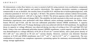
The use of chelated Fe and Mn plays several key roles:
  1. Allows neutral or close to neutral pH. This is because Fe/Mn hydroxides would otherwise precipitate at this pH.
  2. The standard reduction potential of (Fe-EDDHA)-2/(Fe-EDDHA)-1 is substantially lower than Fe2+/Fe3+ due to the electronic effect of the chelating agent. This means that you can add around 600mV to the battery's operating potential. Making it 1.2V instead of the 0.6V that you get between Fe2+/Fe3+ and Mn2+/Mn3+.
  3. Stability of Mn oxidation. Mn3+ is unstable in solution and will react with water to form MnO2 + Mn2+, the use of Mn-EDTA stabilizes the Mn3+ to prevent this from happening. To stabilize Mn3+ without chelating agents, very acidic conditions with other additives (like hydrochloric acid) are needed.
  4. These chelating agents turn all active species into anions. In very acidic solutions using Fe2+/Fe3+|Mn2+/Mn3+ all active species are cations, this means they can cross cation exchange membranes and reduce energy efficiency. By using EDTA and EDDHA, the active species becomes anions (Fe-EDDHA)-1/(Fe-EDDHA)-2|(Mn-EDTA)-1/(Mn-EDTA)-2. This almost completely prevents crossover of the electroactive species across the cation exchange membranes and should therefore provide a higher energy efficiency. With my PVA membrane I observe no crossover of Fe-EDDHA 0.5M over the membrane to a 0.1M NaCl solution after two weeks. Permselectivity values for these membranes are >98% at this pH. Fe-EDDHA has a very high molar absorption coefficient (is very dark red) so crossing of even tiny amounts into a clear solution is easily detectable through Uv-Vis spectroscopy.
  5. They make the electroactive species "bulky" (larger molecular diameter) so crossover of membranes is even harder. This means that chlorides would much more easily cross instead of the electroactive species, if any small crossover happened.
The tradeoff is that the salts are more expensive, the degradation of the organic chelates can lower lifetime and the energy density is lower because the solubility of these chelates is much lower compared with Mn/Fe chlorides.
 
Last edited:
Thank you for taking the time to explain (y).

I'm gonna study the NaCl types to gain a better understanding while following the Mn/Fe development. I like the premises for both.
 
Thank you for taking the time to explain (y).

I'm gonna study the NaCl types to gain a better understanding while following the Mn/Fe development. I like the premises for both.

The chloride types under acidic media could be improved dramatically with the use of an anion exchange membrane (AEM), as cation crossover is one of their main issues. This has been a focus for Vanadium RFB for the past 20 years, but so far no AEM has been found that is stable enough to deal with the concentrated acid plus the harsh oxidizing conditions of the catholyte.

Since anions also have slower ion mobilities compared to protons, use of an AEM would also involve some sacrifice in current density, but this would be more than worth the increase in electrolyte lifetime and energy efficiency.
 
Iron salt battery is interesting for sure. One aspect that I like is that I can take raw iron, plus 30% Muriatic acid (HCl), "shake and blend", vent off the H2 gas and I am left with FeCl in aqueous solution and both are plentiful, easy to get and not too expensive. So an all Iron battery from that perspective is great. This ironically is simpler than locating pure FeCl powder... EU... LOL

I downloaded a few documents, study's and solutions, I think its wise for me to read and get more acquainted, but near neutral pH is attractive.

Crossover or self-discharge is one of the larger aspects that I look at, and "coming from" the NiFe battery with its roughly 3& per month, that is my reference atm. Energy density and roundtrip efficiency are important too but so are system losses.

For flow battery's, we are dealing with two main aspects: The losses in the chemistry (primary) and losses in the system (secondary). The later obviously is the pumps, which is its own topic. So the less losses via crossover there is, obviously the greater the system efficiency and stability. One aspect which would make losses less severe is the fact that with a large enough PV system, input is always greater than losses and consumption, so there is that aspect to consider.

An all iron salt battery have theoretically an endless cyclability since we are only dealing with Fe(II)Cl and Fe(III)Cl speciesism, so the anolyte and catholyte are the same electrolyte, but we could be dealing with a higher self-discharge compared to the Mn/Fe cell (for the time being) which in turn have very low, but instead, potentially, have a lower cycle life due to chelate consuming the Fe and producing FeOx (I think it was) and in so doing, producing pure iron fallout and the cell potential goes down... is that sort of the boundary's we are talking about ??????

I am certainly not jumping the gun or claiming profound problems, just trying to learn and add to the discussion :) - I am not set on needing infinite cycle life, finite if very long, can be fully acceptable. I can certainly look at and work with both types. They might both end up benefitting from that. There are so many aspects to both and flow battery in general beyond just the chemistry - take the ZnBr battery, I highlighted issues earlier in this thread which surpasses the higher energy density and that battery also have theoretical infinite cycle life.

(Saw a video last night about the road towards the All Iron Battery where the iron fallout was mentioned)


That all iron battery has extremely low energy density. In the research he published it is around 0.01Wh/L. Bear in mind that batteries involving Fe metal will always have issues with hydrogen evolution as well. These are the reasons why I didn't consider Fe batteries that do Fe reduction to Fe metal.
 
Got it - I was only pointing to that video for the iron fallout which he talks about and you did too via the organic portion of the chemistry. But what that ultimately mean for your battery remains to see. Also, limited hydrogen evolution is important.

Was gonna mention that the energy density of the all iron battery is too low to be practical. Also, that I love discovering which type of battery's and chemistry is not of interest. :)
 
Last edited:
The issue with hydrogen evolution is two fold, not only does this cause the potential release of an explosive gas, but it also increases the pH of the battery. As the pH goes up, iron oxides and hydroxides can start to precipitate. This is why Fe flow batteries that rely on Fe plating need to have their pH lowered using muriatic acid as a function of time, to replace that lost hydrogen.

To get reasonable energy density from an all-iron flow battery that relies on Fe plating, you need to add a separating membrane - in this battery often microporous membranes can be used, sacrificing energy efficiency - to be able to keep the Fe3+ away from the metallic Fe. When put in contact with metallic Fe, Fe3+ will oxidize it to Fe2+ and reduce itself to Fe2+ as well, basically undoing the charging process of the battery.

With organic chelates, the destruction of the chelates causes free Fe to become available, this can also precipitate as oxides or hydroxides form at neutral pH. The decomposition products of the organic chelate might also be more subject to electrochemical reactions, which might reduce the coloumbic efficiency of the battery slightly.

However, from research done on Fe-EDDHA and Mn-EDTA flow batteries separately, we know that decomposition is slow enough to give us at least 500+ cycles. The batteries did not decay at these points, so much longer tests would be needed to assess the true decomposition rates of the chelates.

Also note, there is no need to buy solid FeCl3 (it is a potentially dangerous reagent as it's a relatively potent Lewis acid). In the EU you can easily buy 40% FeCl3 solution, which is more than concentrated enough to explore these chemistries, you just need to dilute it as needed for use with the acids you want to try.
 
Last edited:
Yes one can buy FeCl solutions but some of them contain sulphuric acid like for etching solutions, so one has to be on guard and check the datasheet and the idea behind synthesising ferric chloride via muriatic acid was such that one ended up with (hopefully) a very pure solution and DI water as a bonus.

RFB chemistry is complex and under development and I am just an eager bystander that is trying to get a grip on the situation. And basically, some chemistry's suffer from non reversible processes like you mention. But its not a matter of if but rather are we getting to a solution that is viable or good enough for a longer period until something better exist - better is probably decades away, at least if we look at the financial injection each system and/or system upgrade would require.

Again, thank for adding to the human pool of knowledge, I sure admire your approach here.
 
I'm here 24/7 to please ;).

Was looking at a paper which use a similar approach as you, but they report crossover contamination form commercial cation exchange membranes. So your PVA based membrane might perform better. Still early days ofc, but its looking good. Also, your cell voltage is higher.


Last edited:
I'm here 24/7 to please ;).

Was looking at a paper which use a similar approach as you, but they report crossover contamination form commercial cation exchange membranes. So your PVA based membrane might perform better. Still early days ofc, but its looking good. Also, your cell voltage is higher.

Note thay those diffusion coefficients are extremely low. From the same paper:

"Within duration of 10 years a crossover of only 0.35 mol% of the initial Fe-racEDDHA concentration can be extrapolated for a hypothetical cell "

Most papers will report crossover values, they have to be analyzed to determine how meaningful they are.
 
Very true and 0.35M% is not a lot

I'd like to get a small setup of mine this spring/summer and start a endurance test. I'd like to start with static crossover as well as doing cycles. I would need two different cell stacks. Both would need to use the same electrolyte batch to eliminate as many factors as possible and let them run independently for say 12 months. If anything happens during this period, then one would be better prepared for a larger system. Time is of utmost importance in my humble opinion.

And if things are discovered and/or improved or resolved on your end as an example, I could simply add another cell stack and start a long term study on it. I have the time to do that.

Q: You don't happen to have 1-2 unpopulated PCB's of the USB battery tester, that I could buy ? ... I can order ofc if you don't have any spare or need them yourself.

Sorry, I don't have any unpopulated PCBs. However, if you're building a DIY potentiostat, I would recommend building the upgraded version they published in 2020, instead of the one I built (https://www.sciencedirect.com/science/article/pii/S2468067220300729). This one has much higher max current (200mA Vs 25mA for the one I built) and will therefore allow you to carry more experiments. I will probably upgrade to this version in the next 1-2 years.

Another important thing if you want to carry out any sort of cycling experiment is that the solutions need to be under airtight conditions and, if possible, under nitrogen or argon atmosphere. This is because the reduced Fe-EDDHA molecule (Fe(EDDHA)-2), is a strong reducing agent and reacts very easily with oxygen from the atmosphere. Note that this is the case for almost any sort of battery where you have something soluble that is a good reducing agent, including Fe2+ containing batteries.

Contact with oxygen in air oxidizes the reduced forms in the anolyte and discharges the battery. This is true for almost all flow batteries where the reduced form is not a plated metal. This process is reversible though, the electrolyte is not damaged by oxygen.
 
Last edited:
A v2.0 version, nice, and the 200mA (not 200mV :)) gives room for greater flexibility, so thanks for the information - wonderful :). Will look it over.

I see, then by that fact, degassing dissolved oxygen (DO) also make sense since cyclability is greatly dependant upon a low amount of DO. Nitrogen is fairly easy to get a hold of, so a nitrogen rich environment or partial vacuum, shouldn't be too difficult either. But yes ofc I am thinking about the 1000 litre tanks already, even if its years away. There is always time to test and develop.. So thanks for the oxygen info, nice bit of info to have moving forward. One could make low O2 content or vacuum monitoring a feature of the anolyte to maintain the longest lifespan as possible.​
 

diy solar

diy solar
Back
Top