Mrdanielmh
Solar Enthusiast
- Joined
- Apr 19, 2020
- Messages
- 177
I hope so!


That's good news!Update from Amy, batteries are just clearing customs
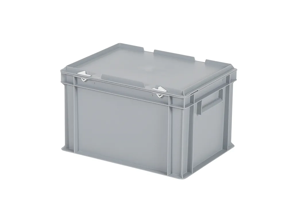
Has anybody come up with a good case solution for these yet?
 www.hulkenbergshop.nl
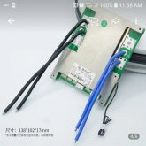
I guess the little black things in the positive output of the battery are fuses?, if so.. why not put only 1 to the main line?. Also this main line should be conected to the battery protect, so it can disconect all the loads if necesary.
I thought it made sense to fuse everything seperately so that if 1 fuse blew I still have other charging capabilities.
I thought the Victron Battery Protect was for load, so I only had it attached to the fuse box load so that it would shutdown access to appliance if the voltage of the battery was too low.
It seems that you may have missed the updated diagram on page 2 where these were removed. The wires you referenced are part of the BMS. They are soldered on the PWB and would probably all receive a ring terminal and be put on the same post. They could conceivably be crimped into a single terminal. Not much chance of single wire failure seeing as though they are only about 8" long.I haven't read through the whole thread so you've probably worked all this out but just in case.
And then I have an open ended question/thought, IDK what the best practice is or should be for protecting the multiple smaller wires going to and from the BMS. If one or more of those wires shorts or opens (and there are 6 individual pieces of wire and 12 total connections), it seems there is at least a theoretical risk of a situation where too much current is forced through one or more of the wires, and no fuse is sized properly to protect the smaller gauge wire attached to the BMS. How are others with similar BMS' dealing with this? Is this a tempest in a teapot or something to take seriously? Seems as a best practice a fuse on each of the 10AWG wires would be the way to go, but maybe I'm overthinking it.
- @Mrdanielmh is correctly using the battery protect, it cannot be used the way @mrdavvv describes because (A) its not bidirectional and (B) it cannot be used directly inline with an inverter
- You are also on the right track regarding fuses, every time you step down to a smaller wire size, you need a fuse to protect that wire, so unless all your wiring is the same gauge as your main battery cable, you are doing it right. But you may also want a main battery fuse (MRBF or class T ideally)
It seems that you may have missed the updated diagram on page 2 where these were removed.
Yeah the chance of a problem is probably pretty low, but still, I think, possible and unprotected. There are 12 potential points of failure (6 solders, 6 crimps, and if the wires are about 8" 6x8" is 4 feet of wire).The wires you referenced are part of the BMS. They are soldered on the PWB and would probably all receive a ring terminal and be put on the same post. They could conceivably be crimped into a single terminal. Not much chance of single wire failure seeing as though they are only about 8" long.
what are you using to draw these nice diagramsHi @loverofpeace - no worries! Here is a zoomed out diagram that I have thrown together which shows the system in a bit more detail!
View attachment 12065
Im still going DIY individual cells, the valance was just for demonstration! Interesting point about fusing the BMS cabless, npt something ive read about before!
Ditto?what are you using to draw these nice diagrams
what are you using to draw these nice diagrams


My BMS has internal over current protection for the BMS sensing wires. In a large pack like my 17S 48 volt pack there is a risk of high voltage, the tradeoff of accuracy is important. A fuse will add unnecessary resistance to the sensing wires and result in incorrect voltage measurements. They do not even recommend cutting or extending the sensing wires.......IDK what the best practice is or should be for protecting the multiple smaller wires going to and from the BMS. If one or more of those wires shorts or opens (and there are 6 individual pieces of wire and 12 total connections)
Ampster beat me to it.My BMS has internal over current protection for the BMS sensing wires. In a large pack like my 17S 48 volt pack there is a risk of high voltage, the tradeoff of accuracy is important. A fuse will add unnecessary resistance to the sensing wires and result in incorrect voltage measurements. They do not even recommend cutting or extending the sensing wires.
My BMS has internal over current protection for the BMS sensing wires. In a large pack like my 17S 48 volt pack there is a risk of high voltage, the tradeoff of accuracy is important. A fuse will add unnecessary resistance to the sensing wires and result in incorrect voltage measurements. They do not even recommend cutting or extending the sensing wires.
The BMS is already controlling the current and has its own protection.
The microvolts of differential between the lines would only be complicated by adding 2 more connections per line with a fuse.
I recommend going to a bus and using a single heavier conductor simply due to the resistance of the wire..
). In either case your system isn't going to spontaneously combust or be drastically less safe either way.Yes, I understand that. My comment was in response to the OP original question about the sensing wires, but the thread has diverge to talk about the current carrying wires and your point is a good one about changing wire size and the need for over current protection for the smaller wires. I wonder how short they would need to be before being joined to a large conductor and could to be considered safe, or at least a small risk?Just to be clear, I'm not referring to the BMS sensing wires/balance leads, I'm referring to the main wires that pass current.


package looks greatAlrighty folks, a great update! I have just taken delivery of my battery cells. Im very impressed withcthe packaging. The batteries arenin fantastic condition andnall measuring 3.33v!
View attachment 14732View attachment 14733View attachment 14734View attachment 14735View attachment 14736View attachment 14737
Next step is to hook these up in parralel and get a top balance completes!