diy solar

diy solar

Chargeverter Woes

Withered+Flame

New Member
Joined
Mar 16, 2023
Messages
30
Location
Alaska
I have tried everything with this setup:

Trying to get the chargeverter to work with 120v.
It shows no amps out and my mulitmeter agrees.
tried 4 amps current, 48v charge, 57v charge, 25 amps current, testing the outlet, and switching it on and off during various points.
Any ideas?
 
If it turns on, then you should have the AC wiring correct. Lights on both boards inside the unit?

I assume you flipped the DC breaker to On. Without a battery connected. You should be able to read the correct output voltage across the DC connection.

You may need to open it up to find out where a connection is not being made.
 
I have tried everything with this setup:

Trying to get the chargeverter to work with 120v.
It shows no amps out and my mulitmeter agrees.
tried 4 amps current, 48v charge, 57v charge, 25 amps current, testing the outlet, and switching it on and off during various points.
Any ideas?
I followed your link and it is showing not available. Might be a defective adapter. Are you getting power through your adapter?
 
I have tried everything with this setup:

Trying to get the chargeverter to work with 120v.
It shows no amps out and my mulitmeter agrees.
tried 4 amps current, 48v charge, 57v charge, 25 amps current, testing the outlet, and switching it on and off during various points.
Any ideas?
That adapter won't work.
You have to replace the plug, on the cord.
 
That adapter won't work.
You have to replace the plug, on the cord.
Depending upon how the amazon adapter is wired, you may be able to rewire the plug on cv.

Move one of the power lines on the cv plug to the unused neutral line. Note: only one of the power lines on the amazon adapter may be connected, so move the non-connected line on the cv plug.
 
Depending upon how the amazon adapter is wired, you may be able to rewire the plug on cv.

Move one of the power lines on the cv plug to the unused neutral line. Note: only one of the power lines on the amazon adapter may be connected, so move the non-connected line on the cv plug.
It's never a good idea to rewire a connection device to some configuration other than standard. Because it can be plugged into the standard and create a Hazzard.
I don't recommend making your own adapter, for the same reason.
The only safe way is to replace the cord end.
 
One other option is what I did.
Wire a generator inlet box outside and wire it to an outlet inside. If you are wanting house power then just ad the outlet instead of altering something that might need a warranty claim.
 
It doesn't use a standard wiring config. It comes with a generator plug with hot hot neutral ground but it doesn't want 120v on the hot and neutral it wants 120v on the hot and hot. The neutral is not connected.

You can install a whole new cord, or wire up a non standard adapter to get 120v hot and neutral onto the hot and hot.
 
It is a standard configuration for 240v.
It needs a new cord end, to be used on a standard configuration for 120v.
A non standard adapter is asking for a Hazzard. That's why you can't buy an adapter for it. (They are illegal)
 
It is a standard configuration for 240v.
It needs a new cord end, to be used on a standard configuration for 120v.
A non standard adapter is asking for a Hazzard. That's why you can't buy an adapter for it. (They are illegal)
Well I would accept that interpretation but the manual specifically portrays a nonstandard pinout option for the 4 prong plug. (It is not illegal to make or sell whatever kind of cord you want, it's a free country. But UL won't list it.)
 
A standard pinout doesn't require that all pins are used. Only that each pin that is used, is used in a standard configuration.
The chargeverter can work with a range of voltage.
You just have to use the correct cord end for the voltage you want to use.
Most of the current led light fixtures are also made to work with a range of voltage.
And use the same European conductor color coding.
Brown, blue, and yellow with a green stripe.
And you connect the power circuit (whatever voltage you have) to the Brown and blue.
 
Right, and the manual has a diagram misusing pins. Go look if you want. Or don't.
It's not.
There are two isolated circuit conductors and a ground wire.
Both pinout diagrams are correct.
 
I guess I'm forgetting that electricians are never wrong, they're just right twice in two different directions.

It's an illegal adapter and a perfectly acceptable relocation of the isolated grounded conductor onto the hot terminal.
 
It's an illegal adapter and a perfectly acceptable relocation of the isolated grounded conductor onto the hot teterminal.
It's not a grounded conductor. Maybe that's where you are getting confused.
The adapter is illegal, because it creates a Hazzard if used for anything else.
Anyone could grab the adapter and think that it's ok to use. Just because the ends match their needs.
This is why we have standards. So that if the ends match, it is safe to use.
 
I don't know why you're so focused on correcting me rather than looking at what I'm talking about. Are you defending this 120v L14-30P pinout?
Screenshot 2023-09-09 at 9.51.30 AM.png
 
A standard pinout doesn't require that all pins are used. Only that each pin that is used, is used in a standard configuration.
If you take the plug that comes with the chargeverter, and move Blue (L2) to not used (neutral), wouldn't that be allowable 120v wiring of the L14-30R, and work with the amazon adapter? Might need moving Brown (L1) instead of Blue, but that should be ok too (depending upon which of the 120v pins is connected to the other end of the cable).
 
If you take the plug that comes with the chargeverter, and move Blue (L2) to not used (neutral), wouldn't that be allowable 120v wiring of the L14-30R, and work with the amazon adapter? Might need moving Brown (L1) instead of Blue, but that should be ok too (depending upon which of the 120v pins is connected to the other end of the cable).
Yes, that would be acceptable.
But if you are taking it apart, anyway. I would just change the cord end. And not need the adapter.
I don't know why you're so focused on correcting me rather than looking at what I'm talking about. Are you defending this 120v L14-30P pinout?
View attachment 166766
I can see how that's confusing.
It would be better if they just gave a wiring diagram. Instead of using a picture of the existing cord end to explain what wires to use.
Maybe even better, if they show a 120v cord end. And which wires go where. That way, almost anyone could make sense of it.
 
Hi All, My Chargeverter is run through an Intermatic 240v timer... *polarity matters*... one way, the unit will not deliver power...
so if you're doing something similar, and the readout shows 0A, try reversing the brown & blue...

If anyone can explain this, I'd be interested. Signature Tech Support could not.
 

Attachments

  • IMG_20231205_125853265.jpg
    IMG_20231205_125853265.jpg
    330.8 KB · Views: 15
Last edited:
Hi All, My Chargeverter is run through an Intermatic 240v timer... *polarity matters*... one way, the unit will not deliver power...
so if you're doing something similar, and the readout shows 0A, try reversing the brown & blue...

If anyone can explain this, I'd be interested. Signature Tech Support could not.
Makes no sense to me.
The Chargeverter polarity does not matter.
There is no polarity with AC current.
 
Hi All, My Chargeverter is run through an Intermatic 240v timer... *polarity matters*... one way, the unit will not deliver power...
so if you're doing something similar, and the readout shows 0A, try reversing the brown & blue...

If anyone can explain this, I'd be interested. Signature Tech Support could not.
So I must have lucked into wiring my 4 correctly? 50% chance. Makes no sense at all, 240v is 240v.
 
I don't know why you're so focused on correcting me rather than looking at what I'm talking about. Are you defending this 120v L14-30P pinout?
View attachment 166766


That is not the NEMA L14-30 I know. More like this:

G - Ground
L - L1
N - L2
not used - Neutral.

Have you put a meter to it? Would seem L1 to Neutral should give 120v
 
So I must have lucked into wiring my 4 correctly? 50% chance. Makes no sense at all, 240v is 240v.

No, you were not losing your mind. I think the thread got confused and . . .

I don't know why you're so focused on correcting me rather than looking at what I'm talking about. Are you defending this 120v L14-30P pinout?

The pinning is exactly the same as a 240->120 EVSE gender bender plug adapter. It doesn't use neutral, so if you want to run 120v you need to tie the 120 volts to L1/L2. Oddly enough Most of the 240v EVSE's are NEMA 14-50, but are happy to allow 120v charging, you just have to make the exact same pin to pin as the chargeverter to get the power on the L1/L2 pins of the 14-50 plug, and your power/wattage is of course halved.

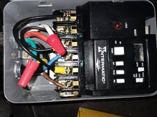
The picture is showing how you would bastardize wire an L14-30 socket which is for a 240v split phase connection, to a 120v feed that would work with the Chargeverter. The Chargeverter like an EVSE is dirt simple. I would use an EVSE gender bender adaptor for occasional use, or replace the pigtail end for a permanent 120v install.
Hi All, My Chargeverter is run through an Intermatic 240v timer... *polarity matters*... one way, the unit will not deliver power...
so if you're doing something similar, and the readout shows 0A, try reversing the brown & blue...

This comment was concerning. Something must be seriously missing here as well. As Tim states, and B-Mod chimes in, AC has no polarity. If you want to get happy this is TRIVIAL to test without blowing yourself up! Grab a 110v 3 wire extension cord and a power strip. Cut the socket off the extension cord, and strip back the wires connect the ground firmly to the hooked prong with a clip, or electrical tape, next firmly attach each of the other two wires to the adjacent hooked prong (Not the smaller one opposite the ground). Now plug it into a power strip and turn the power strip on. The chargeverter will light up. Now turn it off and swap the two hot wires, leave the ground alone. Plug it in, hit the switch the chargeverter will light up.

You could take it one step farther and set the settings very low and charge a battery for a few seconds. This thing is about the same as an old car charger with a rotary switch for current and 6v/12v switch for voltage just with a little more adjustment and a fancier display. You really don't need to overthink it, but the confusion is they are giving you a non-standard wiring method to feed 120v to it via a 240v socket because the unit is fairly agnostic when it comes to voltage. It works fine with anything up to about 250v.

If you think your chargeverter only works when you have the 'Polarity' correct with 240v and you swapped the L1/L2 at a timer and it started working, then I would re-check EVERYTHING, because something was definitely not wired the way you thought. In order for the CV to work plugged into an L14-30 socket, you will need to read the desired voltage between the L1/L2 holes in the socket. Period. That should be the holes adjacent / on either side of the hooked ground pin. Trivial to test with a meter, in fact you'd be remiss if you did not.
That is not the NEMA L14-30 I know. More like this:

G - Ground
L - L1
N - L2
not used - Neutral.

Have you put a meter to it? Would seem L1 to Neutral should give 120v
Your not supposed to really wire an L14-30 socket for 120v this way because it's effing confusing, and your statement is even more confusing because your are not clear. This is the way an EVSE adapter would be wired, but your last line says "L1 (2nd Column) to not used - (Neutral 2n column) should give 120v." L-N = 120v L1-L2 on the socket = 120v Neutral on the socket is not used, but that is NOT the NEMA L14-30 I know. Standard is:
Line - Socket
G - Ground (hooked
L1 - L1
L2 - L2
N - N

So L1-N = 120v, L2-N - 120v, L1-L2 = 240v

A 120v RV pigtail will generally pull L1 and N to get 120v, but there is no "standard" for only picking up 120v from a 240v split phase socket.
 
your statement is even more confusing because your are not clear. This is the way an EVSE adapter would be wired, but your last line says "L1 (2nd Column) to not used - (Neutral 2n column) should give 120v." L-N = 120v L1-L2 on the socket = 120v Neutral on the socket is not used, but that is NOT the NEMA L14-30 I know. Standard is:
Line - Socket
G - Ground (hooked
L1 - L1
L2 - L2
N - N

So L1-N = 120v, L2-N - 120v, L1-L2 = 240v

A 120v RV pigtail will generally pull L1 and N to get 120v, but there is no "standard" for only picking up 120v from a 240v split phase socket.
My comment was in relation to the image previously posted and quoted in my post. Go back and look how the picture is labeled. Clearly says L14-30
 

diy solar

diy solar
Back
Top