Parallel isn't required, panels in series are required to get the voltage to the range where the inverter will operate. You don't have to use both inputs on MPPT 1, you can just use one input if you don't need both. That's why you can just use 10 in series, and have 1 panel as a spare, and not have to worry about mounting an odd number of panels. That distance won't be a problem.The Array will be about 100 to 120 feet from the inverter, I thought on this inverter MPPT 1 had to be in parallel? forgive me I'm reading every day.


You are using an out of date browser. It may not display this or other websites correctly.
You should upgrade or use an alternative browser.
You should upgrade or use an alternative browser.
EG4 18kPV - String Calculations
- Thread starter WattAboutThat
- Start date
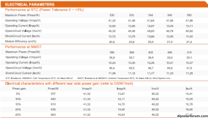
ISC 530 535 540 545 550This is the 18Kpv PV specs.
View attachment 172584
31 panels @ 450W is 13.95KW. That is below the max usable power... so that is fine.
For 8 panels (Single or double string) the VOC @ STD is 49.92 x 8 = 399V. This is well below the 600V max of the MPPTs. It is far enough below 600V that without even doing the calculation I can confidently say there is no cold temp issues. Furthermore, it will remain well within the MPPT voltage operating range.
Could you please provide Isc and Imp for the panels? We also need to know what the backside gain is. (My guess is it will increase the Isc and Imp proportional to the power gain... and they will show a gain of up to 25% )
13.72 13.79 13.86 13.93 14.00
IMP 530 535 540 545 550
12.83 12.90 12.97 13.04 13.11
Thank You
ISC 530 535 540 545 550This is the 18Kpv PV specs.
View attachment 172584
31 panels @ 450W is 13.95KW. That is below the max usable power... so that is fine.
For 8 panels (Single or double string) the VOC @ STD is 49.92 x 8 = 399V. This is well below the 600V max of the MPPTs. It is far enough below 600V that without even doing the calculation I can confidently say there is no cold temp issues. Furthermore, it will remain well within the MPPT voltage operating range.
Could you please provide Isc and Imp for the panels? We also need to know what the backside gain is. (My guess is it will increase the Isc and Imp proportional to the power gain... and they will show a gain of up to 25% )
13.72 13.79 13.86 13.93 14.00
IMP 530 535 540 545 550
12.83 12.90 12.97 13.04 13.11
FilterGuy
Solar Engineering Consultant - EG4 and Consumers
OK,
Here are the full specs of the panels.

for convenience here is the inverter spec again:

I am assuming 2 strings of 8 panels on Mppt1 1 string of 8 on MPPT2 and one string of 7 on MPPT3.
We already determined the Voc was not an issue. I won't rehash that.
Because these are bi-facial, we have to adjust Imp and Isc for the backside gain. They only give data for the smaller panel, but we can see that Isc and Imp increase proportionally to the power gain. (if the gain is 25% Isc goes up 25%).
Edit: Corrected my math. End result is the same.
Now we have to decide what to assume for backside gain. To be safe, we should assume the full 25% gain. Consequently, the Isc for the panel is 1.25 x 14A = 17.5
For MPPT 1 with two strings, that puts the array Isc at 2 x 17.5A = 38A THIS IS A RED FLAG because it is above the 31A limit!!!
For MPPT 2 and MPPT 3, the array Isc is 14A, under the 15A Limit.
I won't calculate Imp for this configuration because we know the configuration does not work.
Note: I calculated backward and a backside gain of only 11% will cause issues with 2 strings on MPPT1. It looks like these panels need to be limited to 1 string on all 3 MPPTs.
So what should we do? Let's look at 1 string of 10 panels on each of the 3 MPPTs.
We already know Isc is OK for a single string, but we have to recalculate Voc.
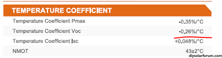
Voc will be 10 x 49.92V = 499.2V. That is just under the top of MPPT operating range and has over 20% headroom for the max voltage of 600V. That looks good so far but we need to look at the temp coefficient and cold temp gain.

With a low temp coefficient of -.26 and 20% headroom, it is doubtful there are any cold temp issues, but I looked it up in this resource and found that the configuration is good to something well below 41F (40C). (That is as low as the charts in the resource go)
So, 1 string of 10 of the panels on each MPPT will work. Great! However, we need to check Imp to see if there will be any clipping. (Clipping means that the MPPT will not use as much power as the panels can produce).
Assuming an array backside gain of 25%, the Imp for each string will be 13.11 x 1.25 = 16.3875. This is well under the 25A usable current of MPPT 1, but it is above the 15A usable current of MPPT 2 & 3.
This means that if the panels are producing at 125% of their rating, MPPT1 and MPPT2 will only use 15A of the available 16.4A. Working backward, clipping won't happen till the panels are producing at 14.4% greater than the STD rating. Personally, I would not worry about it.
Note: There was a lot of math and I tried to show my work to help teach. If you have questions about any of it, please ask.
EDIT: added the following
One more observation. With no backside gain, the panels are at 30x550=16500W. With only 10% backside gain, it will be at 18K and the mpps will start limiting any further gain. 30 of these panels matches the inverter capability quite well.
Here are the full specs of the panels.
for convenience here is the inverter spec again:
I am assuming 2 strings of 8 panels on Mppt1 1 string of 8 on MPPT2 and one string of 7 on MPPT3.
We already determined the Voc was not an issue. I won't rehash that.
Because these are bi-facial, we have to adjust Imp and Isc for the backside gain. They only give data for the smaller panel, but we can see that Isc and Imp increase proportionally to the power gain. (if the gain is 25% Isc goes up 25%).
Edit: Corrected my math. End result is the same.
Now we have to decide what to assume for backside gain. To be safe, we should assume the full 25% gain. Consequently, the Isc for the panel is 1.25 x 14A = 17.5
For MPPT 1 with two strings, that puts the array Isc at 2 x 17.5A = 38A THIS IS A RED FLAG because it is above the 31A limit!!!
For MPPT 2 and MPPT 3, the array Isc is 14A, under the 15A Limit.
I won't calculate Imp for this configuration because we know the configuration does not work.
Note: I calculated backward and a backside gain of only 11% will cause issues with 2 strings on MPPT1. It looks like these panels need to be limited to 1 string on all 3 MPPTs.
So what should we do? Let's look at 1 string of 10 panels on each of the 3 MPPTs.
We already know Isc is OK for a single string, but we have to recalculate Voc.
Voc will be 10 x 49.92V = 499.2V. That is just under the top of MPPT operating range and has over 20% headroom for the max voltage of 600V. That looks good so far but we need to look at the temp coefficient and cold temp gain.
With a low temp coefficient of -.26 and 20% headroom, it is doubtful there are any cold temp issues, but I looked it up in this resource and found that the configuration is good to something well below 41F (40C). (That is as low as the charts in the resource go)
So, 1 string of 10 of the panels on each MPPT will work. Great! However, we need to check Imp to see if there will be any clipping. (Clipping means that the MPPT will not use as much power as the panels can produce).
Assuming an array backside gain of 25%, the Imp for each string will be 13.11 x 1.25 = 16.3875. This is well under the 25A usable current of MPPT 1, but it is above the 15A usable current of MPPT 2 & 3.
This means that if the panels are producing at 125% of their rating, MPPT1 and MPPT2 will only use 15A of the available 16.4A. Working backward, clipping won't happen till the panels are producing at 14.4% greater than the STD rating. Personally, I would not worry about it.
Note: There was a lot of math and I tried to show my work to help teach. If you have questions about any of it, please ask.
EDIT: added the following
One more observation. With no backside gain, the panels are at 30x550=16500W. With only 10% backside gain, it will be at 18K and the mpps will start limiting any further gain. 30 of these panels matches the inverter capability quite well.
Attachments
Last edited:
FilterGuy
Solar Engineering Consultant - EG4 and Consumers
..
FilterGuy
Solar Engineering Consultant - EG4 and Consumers
..
Can you clarify how MPPT1 works @FilterGuy? Can you have a single string that is nominally 25A or must that be split across both MPTT1 string connections so that each MPPT1 PV connection on the 18kPV is nominally only 12.5A? I'm trying to understand if you can parallel two strings at the array itself so you only have to bring single set of cables back to the 18kPV for MPPT1 or if you have to bring both strings back separately for MPPT1.
FilterGuy
Solar Engineering Consultant - EG4 and Consumers
Can you clarify how MPPT1 works @FilterGuy? Can you have a single string that is nominally 25A or must that be split across both MPTT1 string connections so that each MPPT1 PV connection on the 18kPV is nominally only 12.5A? I'm trying to understand if you can parallel two strings at the array itself so you only have to bring single set of cables back to the 18kPV for MPPT1 or if you have to bring both strings back separately for MPPT1.
The MPPTs in the 18Kpv are wired like this:

It really doesn't matter if all the current comes in 1+ and 1- or if it is split between the two inputs. You can put all of the 25A into one of the two MPPT1 inputs.
Thanks! I panicked for a moment I made a mistake since I was wiring it to parallel at the array.The MPPTs in the 18Kpv are wired like this:
View attachment 172649
It really doesn't matter if all the current comes in 1+ and 1- or if it is split between the two inputs. You can put all of the 25A into one of the two MPPT1 inputs.
fromport
Solar Addict
Wouldn't the mppt1 input limit the input current ?Edit: Corrected my math. End result is the same.
Now we have to decide what to assume for backside gain. To be safe, we should assume the full 25% gain. Consequently, the Isc for the panel is 1.25 x 14A = 17.5
For MPPT 1 with two strings, that puts the array Isc at 2 x 17.5A = 38A THIS IS A RED FLAG because it is above the 31A limit!!!
It is the maximum it can use, but I would assume the software of the algorithm would limit that.
ksmithaz1
Solar / EV Junkie
Jeez, I think we continually overthink this. 18KPV max MPPT VOC is 600v, operating is 500v so a 100v buffer or around around 20% well under any temperature coefficient variances unless you are in the arctic or something (Down near -15C with a .5 most panels are even far lower). Panels are ~50v 500/50 = 10 so three strings of 10. If you have a pallet of 31 panels and it's killing you to leave out a panel, pick up a cheapo 48v MPPT for the odd man out. I saw a couple of 48v upconvert units under $100, just nail it to the batteries at 54v or something. Also will give you some experience with non AIO hardware. Actual operating voltage is likely to be in the mid 300's to low 400's at the highest. I've not seen anyone raving about their amazing bi-facial output. Reflected light in my experience is not very useful, but perhaps under ideal circumstances with a ground mount and a highly reflective under-surface, but I'd not bank on any of it. I'd love to see something with actuals on bi-facial output improvement.
FilterGuy
Solar Engineering Consultant - EG4 and Consumers
Don't confuse the usable Imp with the Ioc Limit.Wouldn't the mppt1 input limit the input current ?
It is the maximum it can use, but I would assume the software of the algorithm would limit that.
The Imp rating is just the max the MPPT can use. Going over it does not necessarily damage the MPPT
The Isc rating is a hard limit designed to prevent situations where the MPPT can be damaged.
During normal operations, the MPPT will limit the current to what it can use. However, there is a limit to the MPPTs ability to manage the situation, particularly in transitional states. If the inverter suddenly cuts off the charge current, the MPPT has to follow suit very rapidly. Between when the Inverter changes and when the MPPT can react there can be internal current surges and voltage spikes that can do damage. The manufacturers put hard limits on Isc, Voc, and total watts in order to ensure they can always manage these events.
fromport
Solar Addict
I searched for Ioc limit on this forum but this posting and another looking for specs on PV panels are the only ones that mention it.Don't confuse the usable Imp with the Ioc Limit.
I am not aware of the term Ioc limit, so would like to know more!
So if an mppt input is rated for 3000 watt but you oversize it with 5000 watt but not get near the max current limit, it will not be a problem.The Imp rating is just the max the MPPT can use. Going over it does not necessarily damage the MPPT
The Isc rating is a hard limit designed to prevent situations where the MPPT can be damaged.
During normal operations, the MPPT will limit the current to what it can use. However, there is a limit to the MPPTs ability to manage the situation, particularly in transitional states. If the inverter suddenly cuts off the charge current, the MPPT has to follow suit very rapidly. Between when the Inverter changes and when the MPPT can react there can be internal current surges and voltage spikes that can do damage. The manufacturers put hard limits on Isc, Voc, and total watts in order to ensure they can always manage these events.
But being able to pull more current than the mppt has specified is a problem ?
I Have a better understanding now, that was a lot for you to explain and I really appreciate it. So, I will be doing 30 panels I really don't mind having a spare on hand. These 3 strings will be all in series just to make sure I understand correct. Thanks again.OK,
Here are the full specs of the panels.
View attachment 172648
for convenience here is the inverter spec again:
View attachment 172643
I am assuming 2 strings of 8 panels on Mppt1 1 string of 8 on MPPT2 and one string of 7 on MPPT3.
We already determined the Voc was not an issue. I won't rehash that.
Because these are bi-facial, we have to adjust Imp and Isc for the backside gain. They only give data for the smaller panel, but we can see that Isc and Imp increase proportionally to the power gain. (if the gain is 25% Isc goes up 25%).
Edit: Corrected my math. End result is the same.
Now we have to decide what to assume for backside gain. To be safe, we should assume the full 25% gain. Consequently, the Isc for the panel is 1.25 x 14A = 17.5
For MPPT 1 with two strings, that puts the array Isc at 2 x 17.5A = 38A THIS IS A RED FLAG because it is above the 31A limit!!!
For MPPT 2 and MPPT 3, the array Isc is 14A, under the 15A Limit.
I won't calculate Imp for this configuration because we know the configuration does not work.
Note: I calculated backward and a backside gain of only 11% will cause issues with 2 strings on MPPT1. It looks like these panels need to be limited to 1 string on all 3 MPPTs.
So what should we do? Let's look at 1 string of 10 panels on each of the 3 MPPTs.
We already know Isc is OK for a single string, but we have to recalculate Voc.
Voc will be 10 x 49.92V = 499.2V. That is just under the top of MPPT operating range and has over 20% headroom for the max voltage of 600V. That looks good so far but we need to look at the temp coefficient and cold temp gain.
View attachment 172644
With a low temp coefficient of -.26 and 20% headroom, it is doubtful there are any cold temp issues, but I looked it up in this resource and found that the configuration is good to something well below 41F (40C). (That is as low as the charts in the resource go)
So, 1 string of 10 of the panels on each MPPT will work. Great! However, we need to check Imp to see if there will be any clipping. (Clipping means that the MPPT will not use as much power as the panels can produce).
Assuming an array backside gain of 25%, the Imp for each string will be 13.11 x 1.25 = 16.3875. This is well under the 25A usable current of MPPT 1, but it is above the 15A usable current of MPPT 2 & 3.
This means that if the panels are producing at 125% of their rating, MPPT1 and MPPT2 will only use 15A of the available 16.4A. Working backward, clipping won't happen till the panels are producing at 14.4% greater than the STD rating. Personally, I would not worry about it.
Note: There was a lot of math and I tried to show my work to help teach. If you have questions about any of it, please ask.
EDIT: added the following
One more observation. With no backside gain, the panels are at 30x550=16500W. With only 10% backside gain, it will be at 18K and the mpps will start limiting any further gain. 30 of these panels matches the inverter capability quite well.
Thank You for your help, I really appreciate itParallel isn't required, panels in series are required to get the voltage to the range where the inverter will operate. You don't have to use both inputs on MPPT 1, you can just use one input if you don't need both. That's why you can just use 10 in series, and have 1 panel as a spare, and not have to worry about mounting an odd number of panels. That distance won't be a problem.
FilterGuy
Solar Engineering Consultant - EG4 and Consumers
Sorry. Ioc was a typo. It should have said Isc and I corrected it above.I searched for Ioc limit on this forum but this posting and another looking for specs on PV panels are the only ones that mention it.
I am not aware of the term Ioc limit, so would like to know more!
Note: Ioc would always be zero. (You can't have current in an open circuit).
We need to be specific.So if an mppt input is rated for 3000 watt but you oversize it with 5000 watt but not get near the max current limit, it will not be a problem.
But being able to pull more current than the mppt has specified is a problem ?
There are two different kinds of specs
1) Specs that are limits of what the system can be exposed to
2) Specs that describe the capabilities of the system.
Limit Specifications:
For the 18K pv there are a few limits to what the MPPTs can be exposed to:
- Isc (31/19/19A)
- Voc (600/600/600V)
- Total array PV power for all three MPPTs. (21KW).
Capability Specifications:
For the 18Kpv there are several capability specifications:
- Usable IMP current: (25/15/15A)
The Imp current spec tells you how much current the MPPT will use but does not specify a limit on the solar array. Even if the solar array is capable of producing a higher Imp, the MPPT will not use it. - Usable PV power of all three MPPTs: (18kw)
This spec tells you the total power the 3 MPPTs can generate. Even though the the PV arrays might be able to generate more power, the system will not use it. If the total generated power reaches this limit, the MPPTs will start limiting the amount of power they will harvest from the array. - Full power MPPT Operating Range: (230V - 500V).
This tells you that the MPPT will do power point tracking in this range. However, the system can still work below and above that range (up to the 600V Voc limit).
Unfortunately, it can sometimes be an art to understand what is a limit spec and what is a capability spec. EG4 has been getting better at clarifying this but *all* solar equipment manufacturing companies need to improve.
Last edited:
Hello! Thank you for this great information! I am also trying to do the calculations for my EG4 – 18kPV and have a couple questions.
I am using the Canadian Solar C56W-530MB-AG bifacial panel.
Watts: 530W
Vmp: 40.9V
Imp: 12.96A
Voc: 48.8V
Isc: 13.80A
Here is a link to all of the specs of that panel: https://static.csisolar.com/wp-cont...2/CS-Datasheet-BiHiKu6_CS6W-MB-AG_v2.1_EN.pdf or see the attachment
I have 40 panels but it appears I can only use 38 or 39. (530W x 38 = 20,140W) I would like to configure as follows:
MPPT 1: 9s2p
MPPT 2: 10s1p
MPPT 3: 10s1p
I think that the total voltage of MPPT 2 and MPPT 3 should work at 488V each and MPPT 1 looks good with MPPT 1 having 440V for each string. This should give me the cushion needed during cold temps. However the amperage on MPPT 1 will be above the 25A usable limit but still below the 31A max. Do you think this would work?
The other question deals with the bifacial calculations. I am not sure how to figure that.
Thank you for your help!
Attachments
FilterGuy
Solar Engineering Consultant - EG4 and Consumers
Hmmm.... 488Voc leaves plenty of room to prevent cold weather damage. That is fine. However, with a beta of -.26%/c it does not have to get very cold for the Voc to drift above 500V. I have tried to get more info on what the inverter does between 500V and 600V, but have not succeeded. I have heard that the MPPT will taper the current down as the voltage goes higher than 500V. I suspect that is to keep the total power (V*I) in a range it can handle. What I don't know is how the tapering affects the Power out of the MPPT.I think that the total voltage of MPPT 2 and MPPT 3 should work at 488V each
Quattrohead
Solar Wizard
You should be fine to use 10s with all the strings, the voltage is under the 600 volt maximum that the inverter can handle and it will only pull as many amps as it can use.
FilterGuy
Solar Engineering Consultant - EG4 and Consumers
Thank you for your quick response! Should I decrease MPPT 2 and MPPT 3 to 9 panels? And then what is you feeling about the amperage on MPPT 1: 9s2p?
You should be fine to use 10s with all the strings, the voltage is under the 600 volt maximum that the inverter can handle and it will only pull as many amps as it can use.
Yes, 10 on the strings will work fine. My only question (and I don't know the answer) is what happens to the energy output above 500V.
Similar threads
- Replies
- 65
- Views
- 3K
- Replies
- 18
- Views
- 1K
- Replies
- 10
- Views
- 1K
- Replies
- 5
- Views
- 324
- Replies
- 4
- Views
- 443