diy solar

diy solar

EG4 6000XP AC out load wiring?

MT59918

New Member
Joined
Mar 14, 2021
Messages
26
I have looked but not found any discussion on how to wire the AC output on these inverters to a main circuit breaker panel. I’ve watched a few videos and read through Wills guide on his website and how he did it with 2 6500EX AIO. Would these be wired the same way, taking the 2 load wires from each individual AIO 6000XP to both connections on a 60 amp breaker in an 200 amp breaker panel, and use 1 breaker for each AIO I have? I just ordered 2 of the 6000XP and 2 of the power pro batteries. It looks like the max AC output is 25amps In the manual. Not sure what the 6500’s are. So if my assumption is correct is the 60 amp breaker recommended due to having 2 legs at 25 amps each?

This system will be running an entire off grid home and shop eventually. My plan is to add inverters and batteries each year for a total of 4 inverters and 6 battles is where I want to be eventually. Thanks for any advice.
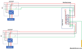
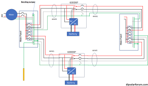
I would wire it with a seperate breaker for each inverter.

1700848606945.png

Notice a few things about this:
1) The internal static bonding relay is disabled in both inverters
2) There is a N-G bond in the breaker box
3) The system grounding electrodes go to the main breaker box
4) The 'main breaker' in the breaker box is either not used or not there.

Breaker size:
The max continuous current is 25A. A breaker for 25A should be 1.25 x 25A = 31.25. Round up to 40A.
 
I would wire it with a seperate breaker for each inverter.

View attachment 179497

Notice a few things about this:
1) The internal static bonding relay is disabled in both inverters
2) There is a N-G bond in the breaker box
3) The system grounding electrodes go to the main breaker box
4) The 'main breaker' in the breaker box is either not used or not there.

Breaker size:
The max continuous current is 25A. A breaker for 25A should be 1.25 x 25A = 31.25. Round up to 40A.
Thanks Filterguy. That’s what I was thinking from what I did find but wasnt sure since the 6000 is a little different than the 6500’s.

I’ll have to read through the manual again and find info in the internal static bond relay. I don’t recall seeing that before.
 
This system will be running an entire off grid home and shop eventually. My plan is to add inverters and batteries each year for a total of 4 inverters and 6 battles is where I want to be eventually.
That seems like too few batteries for that much inverter. Clearly, it depends on your objectives and energy usage, but if you need 24KW of inverter, 20.48KWh of battery seems small.
 
That seems like too few batteries for that much inverter. Clearly, it depends on your objectives and energy usage, but if you need 24KW of inverter, 20.48KWh of battery seems small.
The power pro battery’s are 14.3 kWh each. 6 of them would be 85.8 kWh.
 
I would wire it with a seperate breaker for each inverter.

View attachment 179497

Notice a few things about this:
1) The internal static bonding relay is disabled in both inverters
2) There is a N-G bond in the breaker box
3) The system grounding electrodes go to the main breaker box
4) The 'main breaker' in the breaker box is either not used or not there.

Breaker size:
The max continuous current is 25A. A breaker for 25A should be 1.25 x 25A = 31.25. Round up to 40A.
I am about to embark on this same XP, AC wiring scheme. Please correct me here. The existing house mains panel is to the left of the XP and the newly installed critical loads panel is the one marked "main panel" on the right.

It appears that the AC power just passes through the XP from the grid to the new load panel. Does this diagram show the XP in bypass mode since the second pair of hots coming from the AC side of the XP aren't connected to anything? AND, if the inverter, instead of the grid, was feeding the newly installed load panel on the right, the 2 hot feeds from the XP that are shown NOT connected to anything would then be broken from the grid panel and connected to the 2 hots going to the new loads panel on the right?

Each XP gets a neutral and ground connection from the existing grid panel (pole neutral and ground rod) that are bonded together in the newly installed loads panel on the right.

Thanks for any insight here. I'm ok with electronics, however aside from wiring a few breakers, switches, appliances, etc, my electrical knowledge in this arena is lacking.
 
You might want to go with larger breakers and wire gauges given that although the 6000XP inverter output max is 25 amps, but when in bypass mode it will pass up to 50 amps directly from the AC grid inputs to the outputs.
Agree. The AC Input breaker may even be larger since you can pass through 50a PLUS charge the battery at the same time. Haven’t looked in the manual for this inverter but assume the specs are there.
 
I am about to embark on this same XP, AC wiring scheme. Please correct me here. The existing house mains panel is to the left of the XP and the newly installed critical loads panel is the one marked "main panel" on the right.

It appears that the AC power just passes through the XP from the grid to the new load panel. Does this diagram show the XP in bypass mode since the second pair of hots coming from the AC side of the XP aren't connected to anything? AND, if the inverter, instead of the grid, was feeding the newly installed load panel on the right, the 2 hot feeds from the XP that are shown NOT connected to anything would then be broken from the grid panel and connected to the 2 hots going to the new loads panel on the right?

Each XP gets a neutral and ground connection from the existing grid panel (pole neutral and ground rod) that are bonded together in the newly installed loads panel on the right.

Thanks for any insight here. I'm ok with electronics, however aside from wiring a few breakers, switches, appliances, etc, my electrical knowledge in this arena is lacking.
If the 6000XP's are connected to the grid from the main panel, then the N-G bond is done there and should not be bonded anywhere else - neither in the inverters nor in the loads panel. Note that both neutrals and grounds for the inputs and outputs are both connected to common bus bars inside the units...
 
Agree. The AC Input breaker may even be larger since you can pass through 50a PLUS charge the battery at the same time. Haven’t looked in the manual for this inverter but assume the specs are there.
I just downloaded the manual and it doesn’t specify breaker size. What is the recommended AC Input size? I would assume minimum of 50 (for pass through) but this unit can also charge with grid at the same time it’s doing pass through. Can’t find max AC charging, just overall @125a @ 48v.
 
I am about to embark on this same XP, AC wiring scheme. Please correct me here. The existing house mains panel is to the left of the XP and the newly installed critical loads panel is the one marked "main panel" on the right.
No. The OP specified that this is completely off grid.
 
It appears that the AC power just passes through the XP from the grid to the new load panel. Does this diagram show the XP in bypass mode since the second pair of hots coming from the AC side of the XP aren't connected to anything? AND, if the inverter, instead of the grid, was feeding the newly installed load panel on the right, the 2 hot feeds from the XP that are shown NOT connected to anything would then be broken from the grid panel and connected to the 2 hots going to the new loads panel on the right?
You are correct about how the XP functions.

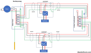
I just copied a diagram I had for modeling the 6000XP. It happened to show the internal relays in passthrough mode. Since the OP specified it was a pure off-grid install, perhaps I should have changed it to this:
1700931813978.png
 
You might want to go with larger breakers and wire gauges given that although the 6000XP inverter output max is 25 amps, but when in bypass mode it will pass up to 50 amps directly from the AC grid inputs to the outputs.
The OP Specified that it was completely off the grid so larger breakers/wires are not needed
 
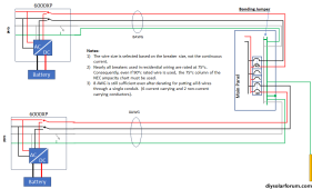
If the system were to be hooked to the grid and the full 50A pass-through is needed it would look like this:

1700933731901.png

Note that for 50A continuous the breaker needs to be 1.25 x 50 = 62.5. For home breakers in the US, that rounds up to 70A... thus the really large wire. I would probably use 60A breakers and 6AWG.... and just accept the slightly lower continuous current in passthrough.

Alternatively, If the sub-panel only has loads the inverter can power, then drop it down even smaller, on the output side it can be 8AWG and 40A breakers. On the input side there are choices. It all depends on how much charge current will be allowed at the same time as a full pass-through.
 
You are correct about how the XP functions.

I just copied a diagram I had for modeling the 6000XP. It happened to show the internal relays in passthrough mode. Since the OP specified it was a pure off-grid install, perhaps I should have changed it to this:
View attachment 179573
Thanks for that FilterGuy,

So just to be clear in my feeble mind: 2 hots, the ground and the neutral all connect to both of the XP's AC inputs and their G&N buss bars from the house/grid panel. Then, the XP's AC outputs, BOTH hot outputs, from both XP's, go to the new loads panel (in parallel) with the ground and neutrals from the XP's buss's, with G&N bonding in the new loads panel as the diagram depicts.

Don't ever get old, 70 is a trying time to learn new tricks. Sometimes I don't know whether to wind my ass or scratch my watch...
 
Just saw the latest diagram.

Oh, the ground passes through, not connected to the XP's. AND no bonding in the new loads panel. AND ground bonded to the can of the new loads panel.
 
Last edited:
Just saw the latest diagram.

Oh, the ground passes through, not connected to the XP's.
The inverters have the ground tied to the case. I should have shown that.

Now that you have it understood.... let me throw in some confusion. ;)

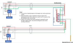
The diagram above is the way most folks would wire it. It is to code and it will function well. However, it creates loops in both the neutral and ground. Loops in an inverter circuit are a great way to create Radio Frequency Interference (RFI) issues. (the code is about safety and does not care about RFI) I would be tempted to break the loops by disconnecting the ground and neutral from one of the inverters at the subpanel like this:

1700938896108.png
The Ground and neutral from the top inverter connect the critical load panel via the main panel and the other inverter.

Note that the ground and neutral for the top inverter are still run, but not connected at the sub-panel. This is my workaround for the places in the code that require the ground and neutral to be run with the hot.

There is an important caveat: If the system needs to support the 50A passthrough, this scheme does not work because the combined current on the neutral of the bottom inverter could be 100A. This only works if the sub-panel is a critical load panel that never draws more than 50A.

Also note that when in pass-through mode, there are still loops in the two hot wires. This is unfortunate, but the potential for the inverter to inject RFI noise is much smaller when in pass-through and it is not generating power.

EDIT: Added the following
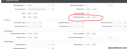
Inverters from some other manufacturers that have issues with flickering LED lights are known to have even worse flickering issues when the loops are broken like shown above. I have not heard reports of flickering issues with the 6000XP, but if flickering is observed with the breaks in the loops, try connecting the G & Neutral back up and see if it helps. (Typically the flickering is worse with low-quality LEDs. Some of them flicker even on grid power.)
 
Last edited:
Back
Top