sunshine_eggo
Happy Breffast!
Same! 
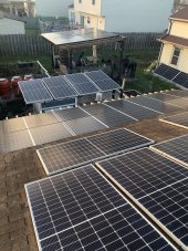
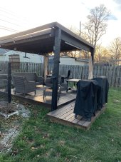
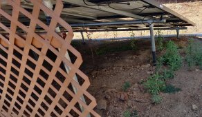
Look at that shading!!!!
Look at that shading!!!!


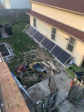
at 45 degrees you'd need ~85 mph to blow them over. flat against the ground I didn't do calculations but it'd probably be like 400mph
yea that is a lot of shade, mine get sun hahaha
I did that once. Grass still hasn’t grown backhey guys OP says not to discuss the systems!
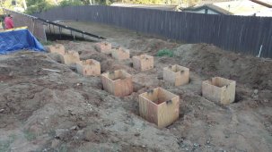
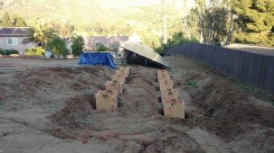
mine is the strongest mount, earth holds them

From my other area the grass hasn't grown back, but I don't want grass either lolI did that once. Grass still hasn’t grown back


 diysolarforum.com
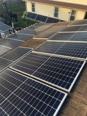
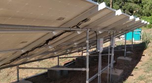
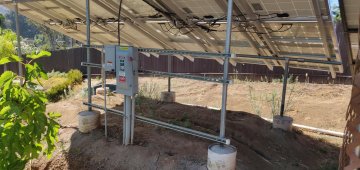
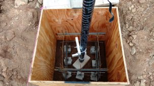
When looking at mount 2-1 the camera perspective and angle of the ground alters the perspective of the phono and our eye. That cross brace is in fact not horizontal and no triangle is formed. It's an optical distortion.Mount 2-1, front to rear brace forms a rectangle and a triangle, subjecting rear upright to torsional loads.
I'd run that from top of front to bottom of rear, for all triangles.
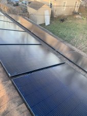
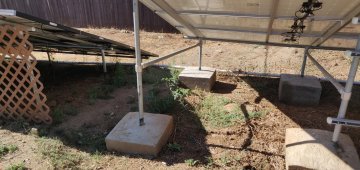
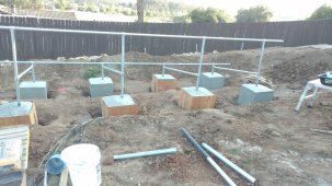
Mount 3-1, no left-right diagonal braces.
I'd add a couple for earthquake resistance.
Mount 3-1, are those Delta LA-602 oil field "silicon varistor" lighting arrestors?
Delta LA 602 Lightning Arrestor "Hey! Is this thing on??"
I've been using Delta Lightning Arrestors on my system since they were spec'd by Real Goods as part of the package I bought from them. I now have a surge capacitor on the AC input as well, which is supposed to slow rising edge of voltage so it doesn't get as high before the Silicon Oxide...
(Be sure to watch Midnight's videos linked in post #4)
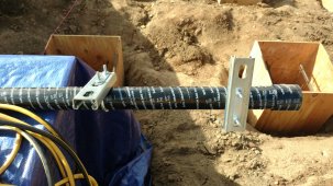
Mount 13-1, I see green wire.
Do you have a wire from PV frames back to chassis of SCC or inverter? If so, good!
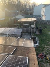
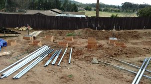
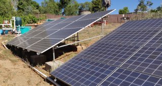
Mount 1-1, are all panels oriented same?
I would have liked some strings oriented SE, some SW, for lower peak longer time of production (depending on usage.)
If net metering, best orientation depends on time of use rates.
When looking at mount 2-1 the camera perspective and angle of the ground alters the perspective of the phono and our eye. That cross brace is in fact not horizontal and no triangle is formed. It's an optical distortion.
Mount 3-1 left to right braces not required for wind loads in our locale. Mount design drawn by a solar engineer and permitted. Each concrete block weight is about 1100 pounds each. That's 6000 pounds of weight and the blocks are 24 x24 x 24 inches, about 10 inches into the ground to prevent sliding.
Yes, those are Delta lightening arrestors. I also have them mounted to Midnite Solar combiner boxes. We get maybe 4 lightening events a year hear and that would be a lot. I know about the Midnite LED, but that simply is not a concern worth the hundreds extra in this locale. But if I was back in Florida, I sure would spend the extra on Midnite arrestors.
diysolarforum.com
All panels face south at 27 degree tilt. Remember, this was 2015-17 and nobody even knew much about net metering 2 let alone 3 and the changes. But yes, today, I would like a Southwest facing array too.
Mount 13-1 green wire: So at each array is a 10 foot grounding rod. Connected to the grounding rod is solid copper bare wire #8 I believe. This wire travels from the grounding rod and is bonded with UL approved ground connectors to each panel. the panels and their connections ground out to the array galvanized pipe and cross pieces. The grounding wire then connects into the Midnite Solar Combiner box which contains a grounding buss bar. The bare wire then completes the loop back to the ground rod, all uninterrupted. The green wire you see is connected to the combiner box buss bar. so is the Delta lightening arrestor ground connector. From the combiner box (which contains Midnite Solar 15 amp fuses for each parallel string, travels the PV +, PV- and the THHN green ground wire into PVC conduit. All of the arrays converge at a Schneider electric DC disconnect switch. The PV+ sides are solar fused across the blade switch, the negative PV passes through and the box is also grounded with a buss bar. This travels into the load center where the ground wire terminates on a buss bar that is also connected to two 10 foot grounding rods at that location connected by bare copper wire into that ground buss. So five grounding rods, 3 at arrays, 2 at the load center and inverter. From the buss bar, the PV wire passes thorough another DC breaker to the charge controllers which accept input as PV+, PV- and ground and output to the batteries as PV + and PV-. It's a little hard to write out, but it works.


I’ll have to take one and post it. It’s just unistrut and wood with some WIP. (Wiring In Progress). I’m not 100% satisfied with the design yet and may add on more to improve integrity. My engineer buddy saw it, rolled his eyes, and mumbled something about four points of contact.Do you have a picture of the back? Would like to see how everything is fastened together. It looks very clean from the front.

Upgraded from 12 305w panels to 14 370w...
Will finish things up in the morning.
View attachment 183200
Are you powering those lights from the solar panels the lights shine on?
(How much electricity can we generate by campfire light?)

? The battery in the light was in fact charged via the old LG Neon's. I have been tempted to throw a 100w panel under some grow lights for experimentation.Are you powering those lights from the solar panels the lights shine on?
How many Peltier modules are we using and what kind of temperature gradients are we working with?(How much electricity can we generate by campfire light?)

Very nice! Any photos from the back?Hopefully it doesn't snow much. Need some dirt digging equipment to make some room for snow shedding
View attachment 183254