diy solar

diy solar

New BMS from IC GOGOGO Store / E&J Technology Group

@Denis , did you receive good support from the IC GOGOGO store?

I read @ghostwriter66 isn't happy with them.

For me overall, they do their best.
And only that is for Chinese AliExpress shops remarkable positive.
Many really just don't care.

The active BMS, to my knowledge 4 out of 4 failed.

I don't know if they are still for sale, the advertisement is still there.
I read about someone who wanted to buy and got response "out of stock".

That is positive.
The idea is good, product not yet.

If anyone is buying, please put your findings about it here!!
 
I returned both of them and I'm waiting for a refund. I tried dealing with them, for them to trade for another type of bms and balancer , but it seems that they are not interested and the communication with them is terrible,I find. It takes forever to get an answer back. Anyways with the transaction of money exchanges,and price change I'm loosing big time, and plus return shipping with tracking is very expensive. Which I had to pay. So no to Icgogogo in the future. I'm still running my system without a bms and everything is going super well. Batteries are really easy to maintain and charge. I'm waiting to see how the smart Daly bms will be, or I will go for another make, like the tiny bms. Thanks
 
Hi guys I was about to order a active bms aswell thanks for the save. I would of brought but for the feedback left. also i love the first active balancer thay brought out. I was looking for a bms
I just found this online it looks amazing a game changer
 

Attachments

  • Screenshot_20200625-202839.jpg
    Screenshot_20200625-202839.jpg
    84.6 KB · Views: 23
  • Screenshot_20200625-202432.jpg
    Screenshot_20200625-202432.jpg
    51.9 KB · Views: 23
  • Screenshot_20200625-202901.jpg
    Screenshot_20200625-202901.jpg
    80.8 KB · Views: 20
  • Screenshot_20200625-202850.jpg
    Screenshot_20200625-202850.jpg
    81.4 KB · Views: 21
  • Screenshot_20200625-202908.jpg
    Screenshot_20200625-202908.jpg
    81.8 KB · Views: 19
  • Screenshot_20200625-201459.jpg
    Screenshot_20200625-201459.jpg
    100.8 KB · Views: 17
Thank you for the Share.

There is a thread for this relative new Daly smart BMS. (Link to forum posts)

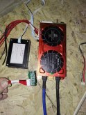
Actually, I have the 150A model right here:
IMG_20200625_220826_copy_750x1000.jpg
(With display and key led 20/40/60/80%) connected)

Smart, not active or passive Balance.
(Passive 0.035mA or so)

If you search for Daly smart BMS you find the thread.

Sadly, while it's Daly product, it doesn't have Daly quality yet!!

Especially the software.
You can read all about it in the Daly thread.
 
Last edited:
Hi, just a FYI
I received my 24s / 1A balance / 300A (Max) Discharge items FINALLY (it took FOREVER)
I ordered two for two 16s LiFeP04 battery packs I have connected to a MP LV5048.
Units have been on-line for 11 days now with no issues.
NOTE: I don't drive them very hard (40 amp charge / 100 amp discharge max).
Here's a screenshot from the app showing 11 amps charging
I have longer than normal cell leads, and the unit is showing a warning that 'Sample - wire Resistance Too Large
Doesn't seem to affect the performance... cannot seem to adjust the value in the interface to 'calibrate' the value to remove the warning.
So-far, so-good
Thanks @fhorst for all the setup tips and documentation in the earlier posts.
made setup a lot easierActive_BMS_Charging_20200626.jpg
 
Good to see it's been updated.
The first batch didn't last 11 days..

The resistance, yes, it is too high.

I extend my wires with about 150cm, using CAT6 network cable.

Soldered the wires from the Balancer to the cat 6 wires.

Make sure they are connected firmly at the base

If you keep having issues, make some conductive grease with pensel scrape (graphite) and silicon oil.

That should solve the issue
Screenshot_20200627_150738_com.jktech.bms.jpg
 
Thay told me the 400amp one is only 200amp continuous so at least there telling the truth
 

Attachments

  • Screenshot_20200627-182121.jpg
    Screenshot_20200627-182121.jpg
    57.2 KB · Views: 22
The resistance, yes, it is too high.

I extend my wires with about 150cm, using CAT6 network cable.

Soldered the wires from the Balancer to the cat 6 wires.

Make sure they are connected firmly at the base

If you keep having issues, make some conductive grease with pensel scrape (graphite) and silicon oil.

That should solve the issue

I would think the other possibility is that the gauge of the CAT6 wires are too small for the run, I believe CAT6 is sold as small as 26-28awg.... you confirm what you have by looking at the wire jacket. I would try a larger gauge wire which should reduce the resistance, 18-20 gauge. OR CAT6 does come in a larger gauge, down to 22awg but can be pricey.
 
@solardad
As you can see at my low resistance using CAT 6, it works just fine.

I have no idea about the "longer" from @John C how much cm - km this is.

A few metres, CAT5 or 6 is just fine.
Same thickness as the original wires.

+10 meter?
22 awg is fine
+50?
Then maybe the step to awg18 is needed.

All the cable need to do is sense voltage and move a few watts (3.x watt. A cell is 3.x volt, 1A,makes 3.x watt)

The "absurd high" (compared to my long wires used with the active Balancer) resistance is most likely not from the length of the cable, but it's connection to the cell.

My active Balancer BMS and the active balancer both had the same values for resistance.

If I make a bad connection, I can get up to 0.8x
Value of 1.x is really high,
Looking at mine average 0.180
 
@solardad
As you can see at my low resistance using CAT 6, it works just fine.

I have no idea about the "longer" from @John C how much cm - km this is.

A few metres, CAT5 or 6 is just fine.
Same thickness as the original wires.

+10 meter?
22 awg is fine
+50?
Then maybe the step to awg18 is needed.

@fhorst CAT6 can come in different versions, CAT6, CAT6a or CAT6e and all of these can have a different wire gauge. I agree that the posters wire length is critical to the resistance equation but understanding the actual wire that is being used and it’s gauge will help determine what is causing the high resistance - both should be printed on the wire jacket. Also agree a poor connection can cause problems and should be one of the 1st checks.
 
Hello. I am using AntBMS for 4 years now. I have the 300A version. I charge daily with 60-80A my battery and nothing happened, although the specs say the maximum charge current is 50A. I can't explain why they would say that.

I opened a lot of these BMS units from AntBMS (all bought from IC GOGOGO) and the bidirectional SSR (that is the electronic switch that cuts the battery from the system either in the charging or discharging direction) is symetrical. Both rows of switching transistors are the same. So why would they advertise 300A in one direction but only 50 in the opposite ?

Even more peculiar is that in the settings, the maximum charging value can be set without any restriction to a higher value (than 50A). Mine is set at 130A.

I did not buy the new active equalizing BMS but I don't think is an overcurrent problem but a driver problem. If it was overcurrent, first the cooling plate should become extremely hot and then they fail. And that should be prevented by a thermal protection. The driver is the part that commands the SSR on and off, gives a wrong command and that has more chance to burn the SSR transistors.
 
Last edited:
Yes, that is correct. If the BMS is in LVD mode, the discharge direction Mosfets are open and the charging current goes through the body diodes. But you also have to keep in mind that once current starts flowing into the battery, the voltage will rise and the LVD condition will not be valid anymore. Thus the BMS will close the discharge mosfets and current will start flowing again through the low resistance path.

But in that short time, the mosfets do have the BMS plate.as a heatsink. It still should stop due to thermal protection. I never saw mine get more than luke warm. Mine also has a casing and a temp. controlled fan.

15938093912026749011942831135537.jpg
 
Last edited:
Hello. I am using AntBMS for 4 years now. I have the 300A version. I charge daily with 60-80A my battery and nothing happened, although the specs say the maximum charge current is 50A. I can't explain why they would say that.

I opened a lot of these BMS units from AntBMS (all bought from IC GOGOGO) and the bidirectional SSR (that is the electronic switch that cuts the battery from the system either in the charging or discharging direction) is symetrical. Both rows of switching transistors are the same. So why would they advertise 300A in one direction but only 50 in the opposite ?

Even more peculiar is that in the settings, the maximum charging value can be set without any restriction to a higher value (than 50A). Mine is set at 130A.

I did not buy the new active equalizing BMS but I don't think is an overcurrent problem but a driver problem. If it was overcurrent, first the cooling plate should become extremely hot and then they fail. And that should be prevented by a thermal protection. The driver is the part that commands the SSR on and off, gives a wrong command and that has more chance to burn the SSR transistors.
Hello @TopCat36 , welcome to the forum.

Please be advised that this is a thread not about the IC GOGOGO store and all types of BMS they sell, but one of their newer BMS, the active balancer BMS.

ANT BMS is sold by them, that's is the only relationship.

To keep the thread clean, I friendly ask you to open a new thread for this question.

Thanks!

I do like the housing on the BMS.
I'll ask a few questions about them in the new thread if you don't mind.
 
I wanted to make a point regarding all BMS with an included SSR switch. Both Active Ballancing BMS and AntBMS work on the same principle. Conclusion was that I do not believe overcurrent was the culprit.

Looking at the photos you made of the BMS PCB, I do not see clearly the SSR. There are some grey sheets (i guess is thermal pad) over the middle of the board. If someone has some photos, would help me get an idea about how the SSR is made.

Also looking at the captures of the APP interface, I see that when the BMS failed, the cell No.1 just showed no voltage. That has nothing to do with the SSR.

A BMS is a protection meant to disconnect the battery in case of failure (of the battery or charger/consumer). In a normal setup, does nothing (ok, for me and many others use it to monitor the cells visually, on an LCD or phone through BT). Why would a BMS failure destroy your cells ? Unless it started active equalizing and remained stuck until it emptied one cell and overcharged the other (which I highly doubt).

So BMS failed, cut the inverter/charger and all stopped. Why puffy cells ? Or, remained closed, inverter/charger kept working but again, the cells were equalized (except one that was defective from before)... why a problem ? The broken cell would overcharge and the rest, not. At discharge, the broken cell gets empty first, gets discharged, the rest not. Only the defective cell would get more beating, not the rest.

All the settings are done in the inverter/charger for charging and discharging the battery, BMS does nothing (in a correct configured system). I am really puzzled how you destroyed 2 sets of cells....

What limits do you guys use for your LFP cells (HVD/LVD) ?
 
Last edited:
I use 3.4 as top and 2.8 as low voltage.

Most BMS use mosfets to switch on or off.

Solid state relay is, as far as I know, quite large, gets hot during contact, and is intended for frequent switching.
Contactors are intended for sometimes on / off.

Mosfet are the cheapest alternative solution.

The thread was intended not to talk about internal functioning of BMS but the active balancer combined with BMS.

That was /is new solution that is great on paper but the first batch sadly bad product.
The newer sold apparently are a lot better!
(Good news)

I'll search if I have some more pictures and send them to you via PM to keep this thread about the active balancer BMS.
 
I arrived on this thread because I wanted to buy an active equalizer, to parallel it to my BMS. I was curious if is worth it to change the BMS also (to have only one instead of 2 sets if wires to the cells) but that is clearly out of the question now. I will buy the 2A, RS485, Active EQ. No point to replace a great working product with a flawed one.

Ok. I will stop here. Only one suggestion. Rise that 2,8. Is a killer. 3,1V recommended and minimum 3V at LFP, if you value your cells. 3,4V absorb and 3,35V float is good.
 
I have their active Balancer 1A.
That works nicely, it for sure doesn't hurt :)

The 1A is continuously 0.5A.
It needs to charge the super capacitor and then discharges, both at 1A.

As the standard Daly doesn't provide any information, the active balancer was a good solution to fill that gap.

My 250A Daly stopped working and is back at them for repairs.
The smart 150A Daly is dramatic product. (See different thread)

I bought the parts needed for the DIYBMS, now waiting for the microscope to solder the 0605 SMD
Normally it's done by the PCB producer, they didn't have that part in stock for long time so I decided to solder myself.

The active Balancer simply uses the same spaghetti wires for the Daly, I connected them all to Cat-6 cable.
Good Tip from @ghostwriter66 :)
It requires some soldering, no biggy.

Active balancer is a good addition

For Lifepo4 the Daly standard stops at amazing low 2.275v ..
(And 3.65 top)
The 2.8 and 3.4 are set in the MPPT Inverter. (16*2.8 /3.4)

Normally my 37.5 kWh never should go that low.
The exceptional time it does, I need that power.
Below 44.8 my generator should kick in.
 
Hi, just a FYI
I received my 24s / 1A balance / 300A (Max) Discharge items FINALLY (it took FOREVER)
I ordered two for two 16s LiFeP04 battery packs I have connected to a MP LV5048.
Units have been on-line for 11 days now with no issues.
NOTE: I don't drive them very hard (40 amp charge / 100 amp discharge max).
Here's a screenshot from the app showing 11 amps charging
I have longer than normal cell leads, and the unit is showing a warning that 'Sample - wire Resistance Too Large
Doesn't seem to affect the performance... cannot seem to adjust the value in the interface to 'calibrate' the value to remove the warning.
So-far, so-good
Thanks @fhorst for all the setup tips and documentation in the earlier posts.
made setup a lot easierView attachment 16254

Are ALL of your wires from BMS to terminals the SAME length .. that is important ...
 
I have their active Balancer 1A.
That works nicely, it for sure doesn't hurt :)

The 1A is continuously 0.5A.
It needs to charge the super capacitor and then discharges, both at 1A.

As the standard Daly doesn't provide any information, the active balancer was a good solution to fill that gap.

My 250A Daly stopped working and is back at them for repairs.
The smart 150A Daly is dramatic product. (See different thread)

I bought the parts needed for the DIYBMS, now waiting for the microscope to solder the 0605 SMD
Normally it's done by the PCB producer, they didn't have that part in stock for long time so I decided to solder myself.

The active Balancer simply uses the same spaghetti wires for the Daly, I connected them all to Cat-6 cable.
Good Tip from @ghostwriter66 :)
It requires some soldering, no biggy.

Active balancer is a good addition

For Lifepo4 the Daly standard stops at amazing low 2.275v ..
(And 3.65 top)
The 2.8 and 3.4 are set in the MPPT Inverter. (16*2.8 /3.4)

Normally my 37.5 kWh never should go that low.
The exceptional time it does, I need that power.
Below 44.8 my generator should kick in.

Which Battery Balancer do you have?
 
Are ALL of your wires from BMS to terminals the SAME length .. that is important ...

It shouldn't matter as it's a somewhat high impedance path (and when balancing you don't really care about voltage drop differences as the BMS can't measure the voltage because of said voltage drop).
 
It shouldn't matter as it's a somewhat high impedance path (and when balancing you don't really care about voltage drop differences as the BMS can't measure the voltage because of said voltage drop).
Depending a bit on the length of the cables and the thickness.

For me I added 30cm on each cell, 2 wires.

My new setup will have 1mm2 wire from the terminal to the BMS / active balancer.
(Actually, I'm building the DIYBMS, that have different setup)
I don't know yet how much it will help the thicker cable and busbars, it should make measurements more accurate.

For the balancing it has almost no effect.

For BMS the same, as I like it to stop at 2.8-3.5
(MPPT inverter settings are set at 10-90%, maybe go in the future to 15-85%)

BMS is last resort, it normally should only be eating dust and never start working at all.
In case of emergency, like your seatbelt, it can safe your battery bank.
 
So If you work with that and with a Victron BMV712 with low and high voltage cutoff, it also works likes a BMS right?
No, sadly it does NOT!

I wish it did.
Lifepo4 (lithium general) doesn't self Balance like a 12v lead acid.
That have 6 cells, if there is voltage difference between them, it stabilise.

Lithium doesn't.
And it does get out of balance.
That's just how it works.
You can't stop this from happening.

With high charge and discharge like electric vehicle, this happens quite fast.

With low charge and discharge (like regular solar use) it goes a lot slower.

But it does get out of balance!!

At the top of the charge, between 3.5 and 3.65v there are just a few ah needed, like 1Ah for 100Ah cell.

When a cell goes too far out of balance, the other cells are still at the 3.49 bump, and a few already passed it, boosting to 3.65.

The BMS should be able to burn of the extra amps for the higher charged cells, giving the ones that are left behind time to keep up.

The cell should not be charged further than 3.65.
If it does damage can / will occur.

The BMS doesn't only slow down the charge of the highest cells, it also stops if one goes too far.

Sadly it can't stop 1 cell, only the whole battery.

One of the reasons for me to have the active balancer.
It helps reduce the (too) high charged cells, and boost the lower charged ones.
Still, depending on your charge speed (and that can be on a sunny day more Amps / watts then you first thought), one of the cells may get close to or pass that 3.65 volt mark

Then the BMS does need to do its job.
If it doesn't, you have one or more batteries in that parallel string damaged, and next day it gets more out of balance due this damage.
As result the next parallel string reached the 3.65 mark too fast, and your damaged string is still on 3.45 ...
(Or even lower, depending on damage)

Your settings on the inverter and charger don't help if the cells are too far out of balance.
As more cells get damaged, more imbalance occur.
Without BMS cell after cell is killed.

Manual monitoring works just as fine, if you stop the charge when it gets too high, and / or burn of the highest charge with resistor.

Most people don't like to watch their battery array so closely.

Bigger array is more stable.

I went from 32*152Ah to 48x, and that already helped.
Next step with 16*280Ah made it even more stable.

I'm still dubbing if I want to spend the money ($1400) to get +1000ah 50 kWh :)
It's now 736, 37.5 kWh

I'm a sucker for round numbers :)

BMS is a must, like your seatbelt.
You never need it.
Untill you do.
The damage without... You really don't want to know.

Safety first.
 

diy solar

diy solar
Back
Top