


You are using an out of date browser. It may not display this or other websites correctly.
You should upgrade or use an alternative browser.
You should upgrade or use an alternative browser.
Anybody tried new JK BMS with inverter communication support?
- Thread starter wepower
- Start date

Unplug the "LAN" cable first before changing the parameter for RS485.
No LAN cable was plugged in when attempting this change. Honestly it's not a huge deal for me as I'll be using CAN, but was just testing. I think the RS485-2 port should be fine for computer comms as even if you have a stack of batteries you will always have a free port.
The manual kind of stinks. I’d like to know more about the heating function as this is the wire included. I’d like to know what the dc wires do and what the max rating is. Also I assume the green is a switched negative but also would like to know the rating.

Steve_S
Offgrid Cabineer, N.E. Ontario, Canada
They haven't even produced a proper Draft User Manual yet, just a basic installation guide.
I won't be doing another one for them and I don't think the other contributor will either.
I won't be doing another one for them and I don't think the other contributor will either.
Well, another interesting thing I found. When removing battery power from the BMS, all the settings revert to default. I currently don't have any batteries hooked up yet, just a power supply to the B- and Bat+ just to play with the software and update the firmware. I have a 4s headway bank for testing 12v stuff and ordered another 4 to play with the BMS. I'll check it once I get those cells from batteryhookup. It would be terrible if this didn't have any type of memory storage.
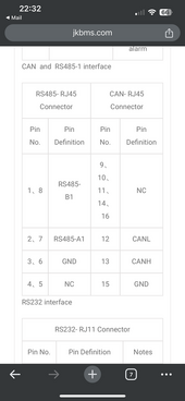
Are you referring to this photo? Maybe this is why I’m unable to get CAN comms to a Deye Inverter.That picture above is wrong. The CAN connector is on the right. Gotta wonder what else is wrong")


I just traced the pcb and yes, the can is on the right! I think I’ve made a huge mistake. ?Are you referring to this photo? Maybe this is why I’m unable to get CAN comms to a Deye Inverter.View attachment 185570
Quattrohead
Solar Wizard
Is it possible that the balance wires need to be connected to retain the settings, JBD takes their BMS power through the balance leads.When removing battery power from the BMS, all the settings revert to default. I currently don't have any batteries hooked up yet, just a power supply to the B- and Bat+ just to play with the software and update the firmware.
Ok, so it’s the RS485-1 port in the photo? I’ll try that port later. what inverter do you have?I just traced the pcb and yes, the can is on the right! I think I’ve made a huge mistake. ?
Nope, I’ve my balance leads connected. Once BMS turns off the values reset to defaultIs it possible that the balance wires need to be connected to retain the settings, JBD takes their BMS power through the balance leads.
hogback
New Member
Yup - should, left to right, 4851, can, 232, 4852, 4852Are you referring to this photo? Maybe this is why I’m unable to get CAN comms to a Deye Inverter.View attachment 185570
hogback
New Member
I believe that's how I did it....
That weird, I normally encounter sending failure if I have CAN or RS485 LAN cable connected.No LAN cable was plugged in when attempting this change. Honestly it's not a huge deal for me as I'll be using CAN, but was just testing. I think the RS485-2 port should be fine for computer comms as even if you have a stack of batteries you will always have a free port.
Oh, before you send the command, ensure all four DIP switches are at bottom.
Alarchist
New Member
The manual kind of stinks. I’d like to know more about the heating function as this is the wire included. I’d like to know what the dc wires do and what the max rating is. Also I assume the green is a switched negative but also would like to know the rating.
View attachment 185500
Green wires heat pad negative, run a separate fused positive to the heat pad, not sure exactly about the red and black, but they're not necessary for a simple heat pad.
This guy wires up a 48v pad with relay:
linkcat
New Member
- Joined
- Dec 10, 2020
- Messages
- 37
I haven't found it, it's really new! If you get one, please tag me!Anyway of getting BMS data into Home Assistant? Is there a modbus address table available?
Well, another interesting thing I found. When removing battery power from the BMS, all the settings revert to default. I currently don't have any batteries hooked up yet, just a power supply to the B- and Bat+ just to play with the software and update the firmware. I have a 4s headway bank for testing 12v stuff and ordered another 4 to play with the BMS. I'll check it once I get those cells from batteryhookup. It would be terrible if this didn't have any type of memory storage.
Thanks for the tip of just powering up the BMS using a power supply to the B- and Bat + ..not connected to any battery I tried the same thing and was able to connect the PC software as i just wanted to update the firmware before trying to connect Batteries but I keep getting the "device identify is not same to connected device" . i even tried the other firmware and also got the same error massage.
Any tips on what to try

Similar threads
- Replies
- 14
- Views
- 826
- Replies
- 3
- Views
- 275
- Replies
- 1
- Views
- 205
- Replies
- 1
- Views
- 426
- Replies
- 10
- Views
- 1K