diy solar

diy solar

Anybody tried new JK BMS with inverter communication support?

Will have to get back to you on this.... no battery connected to the facility right now. But, I think it only showed soc and V. Maybe soh too. However, I never actually tried to set it up in insight local. Do you think I can set it up without actually enabling soc charging?
 
It took JK a long time to come out with a new BMS. The one I'm using (which I think is the latest before this new one) has been around for 4 years or more. This will be amusing.
 
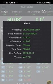
That is interesting. When did you receive it? Can you post a screen grab of the info?
1705134529762.jpeg


I have a 100 amp and a 150 version .. The 100 amp is Hardware Version 14.XA which I got last December 20 . The 150 Amp Version was recived Jan 10 .. Trying to update the Version 15 XA. with current 14.xx files youll get " Major version is not same to connected device"..

Any leads to the Version 15 firmware is highly appreciated .... No luck with getting it off my seller..
 
Not exactly, but just connecting up one jk, I can see it in insight local. Now, I really have no need for a bms to tell my inverter/charger/charge controller what to do when I can tell it what to do, so planning on operating in open loop mode with V control. I've never seen any documentation from schneider to say how they would use any information from a bms other than soc. It does seem like victron can use information about how many bmss it sees, and possibly which ones, in order to lower charging rates if one or more banks/bmss goes down. That could be useful, and would require coordination with the sccs.

Also, schneider allows you to pick only certain 'approved' batteries from their list when commissioning closed loop. I believe this is a regulatory thing for their system to be approved for something or other. My packs will be 6.5kWh ea., and nothing in their list matches that. I'm not sure, but I don't think you can select one of the listed battery models and then change the Ah of it.

I'm totally off-grid, so don't really need soc charging. Both full and empty can be determined by V. Knowing/displaying the SOC would be nice though. BTW, the latest schneider firmware allows for the setting of lbco to 50V, whereas before it was 48V. Useful if you want to extend the life of the batteries at the expense of dod, and don't have grid or ags. I do have ags, so have been setting it to come on at 50.5V I think.

Also totally off grid with the earlier version of the JK BMS 200a/2a and an Victron Multiplus II 48/5000, a smart shunt and 16s 280ah cells and was considering if I can get any benefits with this new BMS and couldn’t come up with anything major.

You guys think I am missing something? What is closed loop charging?

Will probably upgrade to the summer for the fun of it anyway.
 
View attachment 188678


У меня есть версия на 100 ампер и 150. 100 ампер — это аппаратная версия 14.XA, которую я получил 20 декабря прошлого года. Версия на 150 А была получена 10 января. Попытка обновить версию 15 XA. с текущими файлами 14.xx вы получите сообщение «Основная версия не совпадает с подключенным устройством».

Любые ссылки на прошивку версии 15 высоко ценятся.... Не удалось получить ее от моего продавца..
+86 159 6787 7637 Write on WhatsApp. This is support
 
What could possibly make this BMS better?
How about when it’s reached absorption voltage and it reaches desired delta value before it has reaches entered absorption time it simply reverts to float value? Or some other criteria? Anything that gets it charged, balanced and lessens time at higher voltage is the goal isn’t it?
 
What is closed loop charging?
Open loop is where the charging inverter and BMS do not communicate, the inverter charges based on its own settings and it monitors SOC and SOH voltage etc internally. The BMS does not control the charging but has its alarm settings etc so can shut down the battery if say a cell gets out of kilter, it also has its own SOC reading. The BMS SOC and the Inverter SOC can vary a lot between them and result in odd behaviour.

Closed loop is where there are comms between the charging inverter and the BMS, the BMS feeds info to the inverter and tells it how much to charge by etc and the inverter will report the SOC and SOH using the BMS supplied figures. As the SOC on both is identical and from the BMS then less chance of odd behaviour.
 
Also totally off grid with the earlier version of the JK BMS 200a/2a and an Victron Multiplus II 48/5000, a smart shunt and 16s 280ah cells and was considering if I can get any benefits with this new BMS and couldn’t come up with anything major.

You guys think I am missing something? What is closed loop charging?

Will probably upgrade to the summer for the fun of it anyway.
Will YOU really benefits from closed loop? Considering YOUR system probably not. With the Victron’s adjustability in absorb time and tail current combined with the original version JK’s powerful balance balancing power, it’ll handle 99% of the situations. That’s considering that you have the inverter setting optimal for covering your weirdest battery. The closed loop will allow even more variation and aging batteries but then again based on proper settings. It could be said that closed loop adds another link to fail.

My Voltroinc based inverter in open loop/user defined doesn’t allow access to features like absorption time and tail current but it uses a built in algorithm which isn’t perfect. This can be problematic during periods when you have numerous cycles that didn’t attain enough absorption/balance time. When I had the brute power of the Neey 4amp balancer it was never an issue, but then the Daly failed. Now I have the JKs(non-inverter)which works fine for the most part, but there have been a few times in a week of bad weather where the lack of balance time lead to a finish absorb cycle with a delta over 40mv. This was easily corrected the next day while grid charging I temporarily raised the float voltage just beneath the absorb voltage. Only another 45 minutes is all it took. Would this this have corrected itself over time and good weather? Perhaps.
I’m toying around with the idea with getting this newer JK inverter bms on only one battery and use as the master, if that’s even possible. Will it even connect and work with the Solar Assistant or the older JKs?
 
Will it even connect and work with the Solar Assistant or the older JKs?
But do older JKs are chainable communication wise? Probably the only option is to use the "Peter board", showed by the Endy from Off-Grid garage..
 
But do older JKs are chainable communication wise? Probably the only option is to use the "Peter board", showed by the Endy from Off-Grid garage..
Yes, that Peter board is only option to allow multiple "old" JK BMSs to behave as one and use closed loop communication with a system. The problem I saw was that the Peter boards themselves were more expensive then the 100A and 150A new JK Inverter BMSs themselves at least the last time I looked.
 
Not 'chainable' but multiple original JK's can all communicate with Victron together and controlled with https://louisvdw.github.io/dbus-serialbattery/
We're talking about two different things; closed loop and open loop communication. Closed loop is what the Peter boards + old JK BMS support and also what any of the new JK Inverter BMSs support to tell the inverter and charger what to do. Open loop does not tell the inverter and charger what to do. That bus-serial battery code simply reports values to Venus OS but does not support closed loop communications.
 
FYI Helen from JK emailed me (I didn't email them, they must have reached out to buyers of the new bms) and she included the 14.19 firmware with release notes:

-V14.17 Upgrade logs
1.Fixed a bug where parameters were lost after BMS restart. The bug is caused by a logical error in the parameter entered by the user.
2.Change the default configuration parameters to LTO to improve security.
2.Optimized JKBMS Modbus protocol, added RCV RFV register support. The protocol must use the PC software version V2.5.0。
3.Fixed the Bug that the hardware version may be incorrect in the device information.
4.Add battery low temperature alarm to dry triggers.
-@2024-01-09 by JKBMS


-V14.18 Upgrade logs
1.Fix a bug, time calibration may fail.

-@2024-01-12 by JKBMS

-V14.19 Upgrade logs
1.Fix a bug, parameters (RFV Time) Storage failure.

-@2024-01-12 by JKBMS
 
Wow, that's good. Think that's the first time I've seen them proactively contact people. They must be somewhat worried about that one bug and what might happen.
 
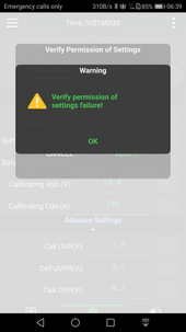
Now that i have the firmware updated. My Bms seems to have forgotten the password for settings that i setup during the 1st powerup. I AM sure i have it right as it is the same as my other devices and have used it a few times during my initial trials .

But today as I reconnected the battery and tried the password verify. It says .

1705317386509.png

I did contact JK and they gave a time bound password that did not work for me . Ill reach again tommorrow.and try again
 
We're talking about two different things; closed loop and open loop communication. Closed loop is what the Peter boards + old JK BMS support and also what any of the new JK Inverter BMSs support to tell the inverter and charger what to do. Open loop does not tell the inverter and charger what to do. That bus-serial battery code simply reports values to Venus OS but does not support closed loop communications.

Dbus-Serial driver IS closed loop! - It does what the 'Peter Boards' do, just use your own RS485/TTL adaptor.. (Only difference being the dbus driver only works for Victron Venus OS)

The driver is very comprehensive, it reads the JK parameters, can adjust charging voltages for both SCC and inverter, depending on SOC, temperature, cell voltage differential etc, and when combined with a battery aggregator driver, all batteries can act as one with the same 'closed loop' controls. Yes, It also reports all this on the Dbus and can be graphed on Victron VRM, Graphana, Node Red. But the whole point of it is to create 'closed loop' communication. It looks more comprehensive than the 'Peter Boards' I'm not sure why Andy didn't bother going into much detail of what it can actually do, but he didn't.

FYI here is the list of default parameters that can be adjusted to allow the serial driver to control your 'closed loop' system:

https://github.com/Louisvdw/dbus-serialbattery/blob/master/etc/dbus-serialbattery/config.default.ini
 
Back
Top