diy solar

diy solar

100A AC ATS

Appears you have separate 100A main breaker.

I just replaced a similar "Federal" breaker panel; in my case a 100A backfed breaker was the main.
Some people consider that brand a fire hazard, and associate it with Zinsco (different style bus), but no apparent issues with mine.


If the breaker panel busbar is 100A, you can install a 20A PV breaker at far end according to 120% rule (which assumes backfeed). That's good for 16A continuous.

Is the wire between your 100A main breaker and the meter accessible?
I'd consider having utility yank the meter while installing a line-side tap going to maybe 100A or 60A transfer switch. That would feed meter.
But it would have ability to draw its current in addition to your 100A main breaker and panel.

Alternatively, I'd consider installing a 100A backfed main breaker in the panel.
Meter --> 100A main --> 100A backfed main.
Then I'd do a load-side tap between the two 100A breakers to feed 100A fused disconnect for inverter.


35kW/day you say? If in summer, about 7kW (STC) of panels would cover that.
Half as much if most days are half and you can switch to grid for those.

How much of the 35kW or 16kW is during early morning/night/evening? That's how much battery you want as a minimum.

With about 6kW peak charging at 12V, that's 500A.
I think you're squarely in 48V system territory.

7kW of PV, 6kW of inverter, mounting hardware and wires, should be doable around $3000 to $8000.
28kWh of LiFePO4 (2x PowerPro) about $8000.
 
@wpns @wheisenburg @Hedges
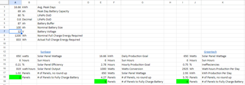
I took a deeper dive into my usage and my calculations. I thought it was a little more straight forward, but it looks like I was wrong so I apologize if I caused any confusion with my needs. I re-looked at my usage history and it seems my average daily kWh usage over the last year is 16.66 kWh. I also confirmed on my utility portal that I use less than 10 kWh per day a significant amount of days. I'm OK with a slightly undersized system and depleting the battery a bit today and charging back tomorrow. I'm also OK with using grid power on those "bad" days.

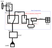
I'm a visual learner, so I am uploading my calcs and my line diagram plan here. You can also see my existing system.

It seems like different sources provide different equations for determining production. As I mentioned, I don't need a complete offset. I'd be OK with 3 or 4 panels to cover the whole day, most days. I'm not sure if my planned location has enough space to put more than that.
Battery Calcs.png

Here's my plan for the system components. Note the blue box are the new components. The red box can be an all-in-one or separate (I'm agnostic). The MSP and LC are existing and will stay as-is.
Wire A is existing, and I will move it to the new ATS.
Wire B will be a short run between the existing breaker in the MSP and the ATS
Wire C will either be part of the AIO or individual wires if I use separate components.
Wire D will be sized based on which voltage battery system I install
Wire E will probably be #10 as I don't see charging more than 30 amps (I have spools of #10 so hopefully I can use them :D)
Wire F will probably be #10 except the PV wire on the roof (again, I have spools of it).
Battery Line Diagram.png

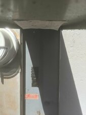
This is the back of my MSP. The white/grey wire coming in from the top is feeding my LC. I will install my ATS here and re-run that feeder wire into the ATS. Excuse the junk :)
pxl_20240605_235829296-jpg.220020


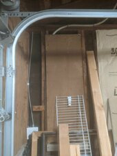
Here is the actual MSP. That 100A breaker is feeding my LC right now. It will feed my transfer switch when I install my system.
PXL_20240606_001925087.jpg

Hopefully this is more clear of what my plan is. I was planning to have a 100A ATS since this breaker is rated for that and it will be feeding my ATS directly, but I can't seem to find it which is the origin story of this whole thread. Being an inspector, in my mind my usage, production, storage, etc. doesn't matter - what matters is what the component ratings are. I know I'll never need to switch 100A, but that is what my system is currently rated for.
 

Attachments

  • PXL_20240605_235829296.jpg
    PXL_20240605_235829296.jpg
    121.4 KB · Views: 36
I can't wrap my brain around 1/2 KWHR of production, a couple of KWHR of storage, 16 or 35 KWHR/day, and a 5KW clothes dryer, 6-7KW(?) of stove, and a 100A (24KW) transfer switch. I mean, your clothes dryer will run your batteries flat in 1/2 hour and it'll take 4 days to recharge them with no other loads.
I'm only sizing my solar and battery to actual usage. The ratings of my dryer, stove, and other loads are not included. I'm not trying to transfer 100A on the switch, I'm only looking for one that is rated for 100A (and more importantly has lugs for at least a #4 wire).
So I read through this and it is unclear to me exactly how you plan to use this switch. A transfer switch has three connections. So, what do you want to do?

I am assuming you want this system for backup only? So when there is AC Grid power available it will connect the grid to your back up loads panel. If you lose power then it will switch over and connect to your inverter output?

If that is the case look for this item from US Breaker NC1D9508-V240. $150.00.

https://www.usbreaker.com/Telemecanique-LC1-Contactor/LC1-D80008-U6/NC1D9508-V240

There are 2 NO and 2 NC contacts. Put the grid inputs on the NO contacts. Put the inverter output on the NC contacts. On the other side of the contactor bridge the two outputs 2 left/2 right together and run to the backup loads. Bridge the grid input to the 240 volt control coil input. So when there is grid power, the contactor will be activated and the grid input will flow to the output side of the contactor. When the grid goes down, the coil will release and the NC contacts on the inverter output will connect to the output side of the contactor. It is probably best to use the side of the contactor with the grid connection as the input side. That way it is easy to wire the control coil. I just crimped the main wire and the control coil wire together with a feral and the put it into the terminals.

These are very heavy duty switches designed to turn industrial motors on and off. They are mechanically linked so there is no chance that the two contact pairs could connect at the same time. WARNING - make sure you understand what these contactors are doing and how to wire them before attempting this. You will need to put this in an enclosure of some type.
This is a very intriguing idea. I want to use my solar and battery as my primary power source and the grid as my secondary. Do you think it would be possible with some controls? Major concern #1 is not supplying power to the grid during a grid outage (meaning if I run out of juice and the grid is down, I'm down too).
It's slightly outside of my wheelhouse, but my electrician could easily do this blindfolded (union electrician for 40 years and specialized in controls).
I just replaced a similar "Federal" breaker panel; in my case a 100A backfed breaker was the main.
Some people consider that brand a fire hazard, and associate it with Zinsco (different style bus), but no apparent issues with mine.
In my solar project manager days, if I saw a stab-lok or Zinsco panel it was an automatic panel change. My boss didn't like it, but I wasn't touching it and neither were my installers. Renting my house, I'm not worrying about it! :D
I actually installed that exact sub panel main breaker today... coincidences!
With about 6kW peak charging at 12V, that's 500A.
I think you're squarely in 48V system territory.
I'm not planning to have more than 3 or 4 panels so 2-2.5 kW of solar charging the batteries so less than 200A based on your calculation even at 12 volts.
EDIT: I was looking at 24V batteries to see what I could get. I found this one which has 100Ah. I would be totally OK with having that as a starting point and if I feel like I need more, I could just add another one in parallel. With 24V, that would only be ~100 amps which I could easily manage with some #4 wire (which I'll be using in the rest of the project!)
 
Last edited:
This is a very intriguing idea. I want to use my solar and battery as my primary power source and the grid as my secondary. Do you think it would be possible with some controls? Major concern #1 is not supplying power to the grid during a grid outage (meaning if I run out of juice and the grid is down, I'm down too).
It's slightly outside of my wheelhouse, but my electrician could easily do this blindfolded (union electrician for 40 years and specialized in controls).

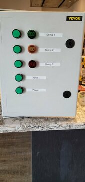
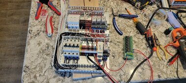
It is very possible to do this with some simple controls. I built the control box below to shed AC coupled PV strings when off grid AND the battery was nearly full. My inverters can supply my control box with signals that indicate the current state of charge > X. I have two inverters so I can get signals for 2 different values. I use > 90% and > 95%. This isn't exactly what you are looking to do, but the basic components would be similar. So starting from the upper left corner:

1. 3 - 2 pole NC contactors, When energized these will open the NC contacts and shut down the attached PV string. The coil for these contactors works with 12 volts DC. You would replace these with the suggested contactor.

2. 3 - 2 pole 12 DC relays, these along with the 240 grid relay have the logic for controlling the contactors and powering the lights. These are wired up so the logic for the lights and the contactors are reversed due to the NC contactor. So when the contactor is not energized the string will be on and the light will also be lit.

3. 12 volt DC power supply and 240 volt "Grid" relay. The "Grid" relay is energized when 240 volts is present on the incoming "Grid" wires. One of the relays poles has a 12 volt grid on and 12 volt grid off signal. The common coil ground for all the 12 volt relays passes through the NC terminal of this relay. When you have grid power, the common will open. No 12 volt relays can energize and all strings will stay on.

You would need to adjust all this logic. For example turn on the contactor when SOC >= 80%. Stay on until SOC < 40 %. This requires a latch circuit.

4. 2 - 2 pole AC breakers. Just basic circuit protection for "Gird" and "Power". Power would be from the inverter.

The DC breakers should match up with what ever voltage is coming in as the control voltage. If you have dry contacts then you can use what ever voltage you like.

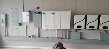
The only tricky thing here is this. You need to match you final output voltage to the input voltage of the contactor coil you use. These contactors are designed to work with AC voltage. So the easiest thing might be to just get the 240 volt contactor and have a final relay that uses your control voltage to switch the 240 volt AC to the contactor coil. I installed the system above the Enphase combiner where I had access to intercept the incoming PV strings.
 

Attachments

  • Picture1.jpg
    Picture1.jpg
    70.2 KB · Views: 8
  • Picture2.jpg
    Picture2.jpg
    98.6 KB · Views: 8
  • Picture3.jpg
    Picture3.jpg
    365.4 KB · Views: 9
  • Picture4.jpg
    Picture4.jpg
    33.5 KB · Views: 8
Last edited:
It is very possible to do this with some simple controls.
This is definitely very intriguing and I know a controls guy who could help me do it right. I've searched for some 100A contactors, but to get anything UL listed is $150 or more. A couple of those and some other components and the cost starts adding up real fast!
Where did you source your parts? I see some Eaton stuff in there, but I can't make out the other items.
Yes 100 amps gets expensive. $550 here:

https://www.boatandrvaccessories.com/products/esco-lpt100-transfer-switch?

Says UL listed.
 
I only see "UL approved".
That's just the manufacturer saying that they think it would pass.
They say "ETL listed" which is just as good as "UL listed".

ETL is another mark using a Nationally Recognized Testing Laboratories (NRTL), in this case Intertek. It has the same exact legal and technical meaning as "UL listed".

I doubt that it can, because it has no mechanical interlocks. (As far as I can see)
If it is ETL listed, it passed and was certified by a recognized NRTL.

A lot of folks say "UL listed" when they really mean "tested by an NRTL to UL standards".

The mechanical interlock is that the relays can't contact both their NO and NC contacts at the same time. A relay is in either state (or moving between them) but can't be in both.

Mike C.
 
This is definitely very intriguing and I know a controls guy who could help me do it right. I've searched for some 100A contactors, but to get anything UL listed is $150 or more.
You should only need one contactor for what you are describing. It is a 4 pole contactor and switch between the two incoming sources. Yes the one I recommended is $150. A good case is $100. The relays and power supplies are fairly cheap maybe 10-20 each. You can use fuses rather than breakers on the incoming power. I think the breakers were 30-40 each. All this stuff might run $350-400.

The thing is if you actually want your transfer switch to have some sort of intelligent control, you would need most of the anyway. You would use the control box to control the transfer switch rather than the contractor. Without some sort of control box a transfer switch would be controlled by a 240 signal. Usually, this would be the grid. When the grid is on switch to the grid. When the grid is down, turn on the generator. The switch to the generator.

Other than the the US Breaker, most all of this was from Amazon. The box I have is just an example of the kinds of things a control box can do. To make your device work, you will need to figure out what signals your inverters can output. Then you will need to design your control logic to operate the switch based on that. Alternatively, you might be able to get devices that directly monitor your batter voltage. Rather than relays a small microcontroller is also an option with the correct auxiliary hardware.
This is still an option. Just covering all of my bases by researching pre-made options...

Has anybody had any experience with the Eaton ATS? Seems like a decent stand alone option that would fit all of my needs.
 
This is still an option. Just covering all of my bases by researching pre-made options...

Has anybody had any experience with the Eaton ATS? Seems like a decent stand alone option that would fit all of my needs.
Eaton is well-known. You can't go wrong with anything they offer.
 

diy solar

diy solar
Back
Top