diy solar

diy solar

2 diy batteries with individual BMS - is paralleling them with terminal bus bars okay?

spearomax

New Member
Joined
Aug 13, 2022
Messages
7
Location
California
I'm building an off grid system in a camper based around Victron multiplus 24v. I've got 16 identical cells from Docan and 2 JK bms. Is it okay to do the following? battery_diagram1.jpgI feel that would be a much cleaner and simpler install than the below which is based off of @Steve_S post #6 from this thread.
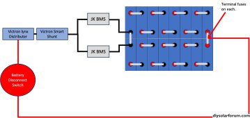
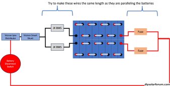

battery_diagram2.jpg

These are not complete diagrams, they are simply the battery connection to the lynx which will distribute power/charging elsewhere. I decided on 2 batteries for redundancy and the possibility that I won't need both. I think my power consumption may be low enough to switch to just one battery and use 8 of the cells for another project. Also everything in the camper can be run on 24v which is nice and convenient.

Thanks for any input.
 
As far as same length for wires goes; the two black negative wires need to be the same length, the two red positive wires need to be the same length, but the black and red sets could be different lengths.
 
I make each battery a completely separate unit, that way I can work on one of needed and still run off the other. Sure enough I often end up changing things, experimenting or adding more batteries so that modular approach comes in handy.
 
I'm in the same situation and am about to build my first bank. Will be going with a 8s2p setup with two BMS units, similar to the diagram Steve provided. As Supra said, basically you are making two separate, functioning batteries and then paralleling them, as many people do with the plug and play styles. Any issues with a cell or the BMS, and I'll take that set offline while still running fine with the other in the meantime.
 
Your 1st picture does not show 2 batteries in parallel. It does sort of but your BMS's are also in parallel. The -ve needs to be joined on the left side of the BMS's, not the battery -ve's.
 
24V requires 8 Cells + 1 BMS.
Options are:
- 1 Pack with Cells Paralleled using one BMS. Not Optimal, especially with anything less than certified Matched & Batched cells.
- 2 Packs with 8 Cells & 1 BMS ea. Most optimal and provides fall back if one pack fails. Also divides & shares Load & Charge.
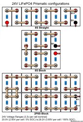
* See battery Pack config image for layout options.
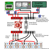
* See generic (Component System) diagram using 12V/4S battery packs as teh example. Same applies to 24/48V systems.

24V Basic Prismatic Configuration.jpg 1694077005580.png
 
You can't OP because either BMS allows full access to all the cells that way, but each BMS can only see half of them.
 
So in the diagram by steve, the negative wires coming off the battery are from the P- side of the multiple BMS's? Can I attatch all to a smart shunt or should I do bus bar in between?
 
Probably best if you draw up another one of your diagrams for us to comment on. One of Steve's diagrams portrays 3 12v banks paralleled, so is not directly applicable to your situation.
 
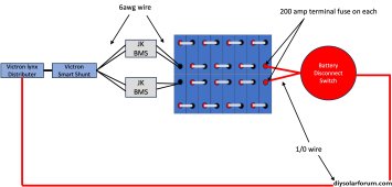
Good idea. How does this look? I bought 1/4 inch lugs for 1/0 wire so I could use 1/0 for BMS connections, but curious if you all think two 6awg wires on each side would be fine (combined wire guage calculator says this is equivalent to 3awg which should handle 100amps fine). As a reminder this is a 24v system with 3000w Victron multiplus. Thanks for any other input. Great community here. battery_diag_wire_question.jpg
 
Back
Top