diy solar

diy solar

My jk 200amp bms didn’t come with bolts. What’s the size?

Azguy82

New Member
Joined
Mar 3, 2021
Messages
29
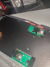
What size bolt do I need for the jk-b2a8220p

I’m doing 8 cells at 24v. I think I’m gonna do 8s, I have 2 bms’ so I can do 4s but I think for balancing 8s with 1 bms is better correct? Also I’m going 24v on the bank so I think with a multiplus 2 I’ll prob only pull 150 amps max from it at any surge.

I was thinking 2x 2awg wires would be enough for 150amps.


What’s the bolt and thread for these? I bought from docan and only got the balance wires and temp sensors… no wire lug or bolts.

I’ve looked it up and almost all the posts are about the wire size or doing a 2 into 1 set up.

Thank you.
 
2x2awg is way more than enough for 150a and would be very compatible for the 200a BMS.

I thought they were m6 or m8 bolts.
 
Hello Azguy82. If this helps you, I had the exact same problem - I ordered 8 of the EVE LF280K V3 Grade A Cells, and the JK-B1A8S20P BMS and...no bolts for the BMS??? What?

I had to steal 2 bolts from the EVE cells to get the pack up and running. Fortunately, these are the new style battery terminals with two bolts per terminal.

I found the solution here:
Belmetric is awesome! I could not find these 12mm length bolts anywhere else. Well, not only were they perfect for the BMS, they are the exact same size of the bolts that came with the EVE cells.

I ordered 68 of them - 4 for the BMS terminals, and 64 so that I have enough for 2 more 8S packs of the EVE cells (probably won't need them for cells), or just to ensure that I never run out of them for future BMS units. I like JK. Belmetric got them to me in 3 days.

JK needs to get their act together and break down and provide $2.24 worth of bolts with their BMS.
 
Last edited:
My 200A 4s JBD didn’t come with bolts.

Should they also include lugs as well?

I’m all for one stop shopping but I’m cool with them skipping the hardware, def not a deal breaker
 
Hello hogback, as for torque, the specs for the EVE LF280K V3 state 6 Newton Meters max.


I tighten mine to 5.6 Nm.

It is good to see someone asking that question...I am no expert, but I see too many people posting and saying that they stripped bolts or studs...really? That is why it is so important to have a torque wrench and know what the manufacturer or vendor states.

I am thinking that people might have issues with resistance measurements from buss bar to terminal, and their solution is to keep tightening until they get a better reading...NO! Wrong solution.

Maybe they think over-tightening will lower the cell deviation delta in millivolts.

If you tighten to spec and still see problems, I think it is time to remove the buss bars, examine for burrs or imperfections and clean the terminals and buss bar mating surfaces (at least with alcohol). Then reassemble and see what you get.

Another one that might get them is that, with a BMS such as the JK series, the sense lead resistance is in the stats of the management UI. Maybe they think that tightening the bolts more will bring the resistance down? No...time to examine crimps and ring terminals.

I can only speculate as to their motivation to tighten to the point of stripping threads.

Stick to sane torque values and you can't go wrong. I say that 4Nm to 6Nm should be good in most situations. Andy over at Off-grid Garage seems to tighten to 4Nm by default.
 
Oh, I should add...There are warnings in posts on this forum about using the wrong solvents/agents to clean terminals and warnings to NEVER use power tools to clean terminals (not even Dremels). These warnings are generally issued by people that display a great deal of knowledge.

From what I have gathered, it seems that 97% alcohol and vinegar are really safe to use. These are the methods that I use and Scotchbright seems to be the preferred, abrasive scrubber.

Now, this is just my thinking and I could be wrong, but I think that using a buffing pad on a Dremel would probably be fine. That is just my opinion and I don't KNOW that, I just THINK that.

I think that what the posters of those warnings are conveying is, to not use a power tool with any kind of sanding disk or drum, and not to use wire wheels.
 
I know there are some generic torquing spec for electrical connections for nut-on-lug types, but usually these are for rigid posts/studs, and not some much weaker pcb mount stuff. I think the jk terminals are m6.
 
Oh, Hogback...sorry...I did not assume that you are not aware of those things. I wrote that response for the benefit of those that might stumble across this post. I hate to see people just building packs for the first time and they harm their brand new batteries. I would cry if I hurt my new batteries. ?

Yes, they are M6. If you follow that link to the bolts available at Belmetric, you will see M6, 12mm length, 10mm hex. They fit the new style terminals perfectly since they are the exact same length as the OG bolts from EVE and the bolts are perfect for JK terminals.
 
Phillips, hmmm...I suppose that could work out. I think I would put a Phillips 1/4" socket drive on a Nm/Inch Pound torque wrench and put good pressure against the screw head to avoid any possible stripping. I think I went with 4.5 Nm on those bolts. Those terminals after all, appear to be bonded and soldered to the board...I would not press my luck. ?

If you had to, you could probably get them out with long nose Vise Grips should you strip the heads. I was concerned about the thread strength on those terminals so I went with 4.5 Nm to be safe.

However, preferably I would visit that link I posted and get those bolts so that you can use a 10mm socket instead. They are dirt cheap and Belmetric is awesome with packaging, they deliver fast and they are a reputable online source that does not spam your mailbox.
 
Last edited:
Oh...I see now...yours has a different design than mine. Here is a picture of the one I have (JK-B1A8S20P):

1704943651297.png

This is a 200 amp BMS so they wisely chose to provide two terminals per side to allow two smaller conductors such as 2 4 gauge wires. I think that is a much better solution than trying to bolt huge wires to two terminals.

I think that with yours, it is really important to torque it with a proper wrench. I reckon that several people likely striped those terminals with brute force, or possibly ruptured the solder joints holding them to the PCB.

They still look strong and capable, they just require following the torque spec. I would look that up if I were you and see if some source on the Internet has the answer.

If you don't find anything, I would not go more than 4Nm on those. Andy at Off Grid Garage torques cell terminals to only 4Nm and he has great results in capacity tests and cell voltage deltas. Then again he has tons of experience and knows that if he sees something funny, it is time to investigate...not keep tightening.
 
Last edited:
Oh wait...just zoomed in on your image again...they wisely chose to put holes in the PCB so your screw could pass through if it were a bit too long. I think you would probably be good with my fastener recommendation.

Good call by JK to have those holes to pass through. :cool:

Another cool thing...if you could get your hands on another pair of those terminals, and you are good with a soldering iron you could solder them in and have two terminals, allowing you to downsize your conductors and use two per side instead of just one.

If you have the experience and a good, powerful iron then you would have no problem. Where most will get into trouble is having a weak soldering iron.

Something like that requires high heat/short time duration. The weaker the iron, the more prone to damage...could result in holding the iron too long on the terminal and possibly causing clad to lift from the PCB. The other possibility is a bad, cold solder joint that would not properly pass current.
 
Last edited:
I will tell you one mod that I will likely perform on my BMS...slap some good sized heat sinks on that metal casing. I reckon the FETS can withstand the heat and perform to spec, but in my experience, the cooler you can get them to operate at the same load, the longer they will last.

If I do it, I will record before and after temps of the FETs that I can hit with an IR temp gun, on the sides where there is an air gap. I will use a constant load at a given number of amps.
 
Last edited:
Hey hogback, I am fairly certain that you meant that you have a JK-B2A8S20P, is that correct? Notice the 'S' instead of an '8'.

What year did you pick that up? I wanted to find it online, however all that I can see are the ones that look like mine, except they have 2A balancing current. It appears that they changed that model.

BTW: I edited my last two messages...I was long winded and went off topic. :fp2

The whole point was that, modifying that board and adding two terminals would allow two 4 gauge wires instead of having to run a 1 or 2 gauge wire.

According to this calculator: https://www.wirebarn.com/Combined-Wire-Gauge-Calculator_ep_42.html

2 x 4 gauge wires = 1 gauge
 
Last edited:
It's the latest jk inverter bms. I'm going to use 2awg wire, as I already have it, and prefer the simplicity of fewer wires - these are going to be crammed in a relatively small space. The flexibility of thinner wires does have a benefit here though.
 
It's the latest jk inverter bms. I'm going to use 2awg wire, as I already have it, and prefer the simplicity of fewer wires - these are going to be crammed in a relatively small space. The flexibility of thinner wires does have a benefit here though.
Ah...yep, no sense in not using 2 gauge if you already have it. :cool:

But it is a really cool feature that JK built that board with the capability to add an additional terminal if you wanted to go the 2 conductor route.

I just like things that have options. The way that JK built the metal covers/heatsinks totally flat makes it easy to mount additional finned heatsinks and dramatically bring down temperatures. I am going this route and I will also add a fan. I will post results in a new thread.

Good luck with your system and you have a new fiend here at DIY Solar.
 
I thought I would pass this on, since this is the ONLY place I found an actual manual for my BMS and yours:

 
Back
Top