diy solar

diy solar

2 Millisecond short

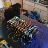
Testing resistance... you might want to to that under some sort of load - carrying the same current you plan to when using them.
The thing is, with those... you'll see if you replace the wires... for one thing they tend to be badly crimped, for another, the wires themselves are so thin, you can use them as fuses (if you don't mind the burnt rubber smell ;·). Anything over 2-3 amps going through them will melt them. :·)
-
 
To add a bit more insight the the charging system voltage. There is almost no chance that you will get all 4 series cells to hit 3.65 volts at the same time. You'd be better off to set your charging system to something like 13.8-14 volts (3.5 x 4)

If you charge to 14.6 volts, you're very likely to have a cell go very high while the other 3 stay lower. Or if you do end up with a BMS, it will disconnect.
 
You could use a cheaper, small, separate port BMS to trigger a high amperage relay between your alternator and battery bank. That would allow a high voltage disconnect on the charging side in the event of cell drift.

You could also do the same thing between the battery and your amplifiers. It would allow virtually unlimited charging and discharging current through those relays.
 
I'll charge all cells individually to 3.60 then passively balance them and top them off like I did with the LTO bank.
Just out of curiosity, why don't you just wire them all up in parallel and then charge them to 3.65V like most folks do to top balance? You would get a better result that way.
 
I have seen successful installations without a BMS or balancers. It can be done. Just because it can be done doesn't mean it should be be. To be successful without a BMS requires a Thorough understanding of the issues, and taking precautions elsewhere in the design. Just slapping cells together without a BMS will surely damage them, which MadMax03, by the voltages you posted you have already done. Probably not so damaged (yet) that you need to replace cells, but if that happens a couple of times you will. A BMS would have prevented that.

There are BMS systems that will handle over 500A. Using very high output alternators on LFP is not unique either.

I would not rely on car audio guy YouTube channels as a source of expertise.
 
Ok, we are balancing. I'll let that sit for a couple days and see where we're at. Then I'll work on charging, then top balancing.
 

Attachments

  • IMG_20220406_104031.jpg
    IMG_20220406_104031.jpg
    190.5 KB · Views: 28
That's Stimpy, he's not going to let me make anymore mistakes on this build. I just hope he doesn't rip the fun chewy jumpers off and short anything out. Fried kitty cat!
 

Attachments

  • natlamchristmasvacation03.jpg
    natlamchristmasvacation03.jpg
    52.1 KB · Views: 21
Passive balancing by connecting in parallel ain't gonna do much. They're at a settled voltage, and won't source much into each other.
If you connect a CV/CC power supply after setting it to 3.5V or 3.65V, that will do much more, raise the lower ones to match the higher.

What voltage do they show now?
Voltage vs. state of charge diverges more past the "knee", which is somewhere around 3.3V or 3.4V. Below that, practically same voltage regardless of SoC so no balancing.
 
So just start by charging them individually with the power supply to 3.60 then top balance?
 
Passively balancing like this put them all at exactly 3.272 the first time I balanced them. I let them sit for a week.
 
All top balancing means is filling each cell full so that when they are assembled as a pack the pack has the capacity of the weakest cell, which is as good as it gets.
No magic occurs when cells are paralleled.
 
Someone here (forgot who, sorry) has been known to quip:
“Batteries don’t die, they are murdered.”
Someone might have mentioned this already but I first saw that quote from one of the Otherpower guys from about 17 year ago.
 
To top balance, you need to get all the batteries at exactly (or as close as practicable ) to the same voltage, at the top of the voltage curve. Anywhere after the curve gets steep is fine, so there is little advantage to top balance over 3.55v per cell or so, although 3.65v is the standard voltage.

This charging can be done by individually charging each cell to 3.65v, or they can be paralleled and charged together. Charging individually takes longer, and it is difficult to precisely get the batteries exactly the same- but small differences in voltage once you are 99% charged will make little to no difference in the performance of the final pack.

Those jumpers make me cringe. For accurate top balancing, using larger wire with bolt on ring connectors works much better than tiny wires with alligator clips. The thin wires and clips create a significant voltage drop at higher charging currents.
 
Ok, we are balancing. I'll let that sit for a couple days and see where we're at. Then I'll work on charging, then top balancing.
Oh my goodness, alligator clips with small gauge wires, those wires are not likely to be soldered to the clips either.
 
I'll pull the jumpers then and start charging each cell to 3.6v
Leave the jumpers on (assuming they're all connected in parallel) and then attach your power supply also. The idea is to charge all of the cells at once to 3.6 volts.
 
Back
Top