timselectric
If I can do it, you can do it.
- Joined
- Feb 5, 2022
- Messages
- 19,671
Sure it can.So, a lone inverter can not by it's self make a phase?
A single phase
Some can make 3 phase too
Sure it can.So, a lone inverter can not by it's self make a phase?
The high side of the above transformers are wired in a wye configuration and will function independently and absent either or both of the other two phases.
It takes two legs to make a phase.The high side of the above transformers are wired in a wye configuration and will function independently and absent either or both of the other two phases.
What would be the difference between the terms 'leg' and 'phase' here?
Looks interesting to me.Not really.
It's fairly simple, once you see it.
My work is done, here.
I believe, with enough time to think about it.
Everyone can eventually understand.
Being able to use the outputs of two HF inverters nowadays to create a 120/240v feed is pretty nifty. Bit beyond me how each inverter syncs up to product the 180 out of phase outputs. Electronic magic.So, a lone inverter can not by it's self make a phase?
Not really.
It's fairly simple, once you see it.
My work is done, here.
I believe, with enough time to think about it.
Everyone can eventually understand.
I guess you are kind of on to where my thought is coming from.If it's "2 phases 180 degrees out", and 3 phase is 120 degrees out, how am I able to get "2 phase" out of a 3 phase transformer?
The peaks wouldn't line up at 120 and 180
I think it only works if we have 1 phase.
Not exactly. The center tap (halfway across the single phase), makes it split-phase. In most cases this conductor is also bonded to ground ( AKA, a neutral). But it doesn't have to be, for a split-phase configuration.Seems like there are and always will be lots of split opinions, it's a never ending phase.
My rookie understanding is you can't have split phase without a neutral. Would that be correct?
3 phase requires 3 legs. If you lose one, you are left with only 2 legs. Two legs gives you single phase.If it's "2 phases 180 degrees out", and 3 phase is 120 degrees out, how am I able to get "2 phase" out of a 3 phase transformer?
The peaks wouldn't line up at 120 and 180
I think it only works if we have 1 phase.
3 phase requires 3 legs. If you lose one, you are left with only 2 legs. Two legs gives you single phase.
The reason 3 phase is used is because it's cost effective. Just by adding one more conductor, you can carry 3 x as much power.
A sign wave travels through 360 degrees, from peak to peak. 3 equally spaced (timed) sign waves are 120 degrees from each other.
Single phase power flows in one wave.
Think of split-phase as two people riding a tandem bicycle.
As they pass by you, for a split second. It would appear that one person (front seat) is traveling away from you. And the other person (back seat) is traveling towards you. But they are both traveling in the same direction.
The point of reference can change what you see. But it doesn't change what is actually happening.

You are very close.I guess you are kind of on to where my thought is coming from.
If you were referencing a 120v phase to another phase of three (120 degrees out), you would see 208v (120*√3), but 120v to a system neutral in a Wye system.
In a Delta system (has no neutral or reference to ground), if one of the three phases are lost, it's said that you would now have only single phase available. Either system needs a return path to function.
The pad-mounted 3∅ transformers I work with all have three separate transformers wired inside the oil filled case. Just like you'd see 3 overhead transformers clustered together on a pole. In this Wye transformer, if a phase is lost up stream (even at the sub station), you will still get 120v to the neutral on each of the remaining phases and 208v across the two phases.
The reality is that three phases were created simultaneously at the generation plant and never existed individually (as it was designed and wouldn't work if it lost a phase there). In a solar field, the individual phases are created separately and would be usable, even if the other two phases were absent.
Or am I missing some basic thought here?
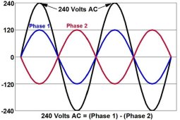
If you change the 240v labels to 120v, and remove the 120v labels. And remove the red and blue waves. Then you would be accurately displaying split-phase configuration. There is only one phase.Agreed. I think people might be confused because the time function is the same.
Split phase 120 sine waves overlay the 240V waves its just that the waves aren't as tall because the voltage is less due to only using 1/2 of the transformer.
I like this graphic.
View attachment 125209
If you change the 240v labels to 120v, and remove the 120v labels. And remove the red and blue waves. Then you would be accurately displaying split-phase configuration. There is only one phase.
Hopefully, this has helped some people.
If so, then it was worth the effort.
I still do, occasionally.I'm still going to shock the shit out of myself regardless.
14,400v on a wet day with gloves and di-electric bucket truck can be shocking all day.I still do, occasionally.
Even after 38 years of practice. lol
Thank you.Hopefully, this has helped some people.
If so, then it was worth the effort.


