diy solar

diy solar

25kWh daily output, but I only used to need 10kWh per day.

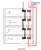
View attachment 129133This is what the SunSynk manual recommends (the lower right diagram, 'Max 200 Amp') for connecting multiple batteries (I have three 5kWh ones) to the 8kW Sunsynk. I've asked my electrician about it.
If you want to daisy chain them like that then connect the inverter cables at opposite ends. If you connect to multiple inverters then you'll either have to get creative with your connection points (with two inverters and 3 daisy chained batteries then you can connect one inverter to the top and one to the bottom) or you'll want to add busbars.
 
@SenileOldGit Hello,

My opinion how to connect battery in parallel is only this way:
1675468416718.png

Reason is Ohmic law. Imagine the situation where is your connection. Battery number one have shortest connection such as possible. Next batteries have longer and longer connection. Battery #1 is most exposed by peaks.

My connection sketch comes out from the same length of cables. But this solution still have no optimal impedance for batteries in the center. But for four pieces is enought.

Wire width is so much important. I have seen some "shoelaces" on the pylontech batteries. My recomendation you need use 50mm2 (0 or 00 in AWG) plus wire for 200A peak currents.

When you use thin cables, then voltage drops on the cables will high** and inverter will not be happy.

**High drops I mean 1V+ peak drop on the cables (fuses, switch,..). Everything is important. You need some superconductors :) for hi currents.
 
@12VoltInstalls Hello,
When You use schematics, which I draw in my previous comment, it will work OK. But two middle batteries will be used with slightly less power due to ohmic law.

I have seen that phenomenon when I formated the LIFEPO Cells for my power plant. I used the same connection, but I used 16 cells. I have seen slightly less voltage on cells connected in middle of the wires.

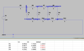
I made some simulation on LTSPICE. I set every resistors to 1 Ohm for clear result (in reality impedance of battery or cells is many times higher, than wires).

Resistors R1,2,3,4 represent the BATTERY, other resistors is wires.
You can see the voltages measured in schematics.
Again: In reality this phenomenon exist, possible to measure. But it is not critical.
If you want to avoid that phenomenon, you must connect each battery with wire to common node with the exact same cable length.
1675546281949.png
 
When You use schematics, which I draw in my previous comment, it will work OK. But two middle batteries will be used with slightly less power due to ohmic law.
My point was you CAN wire them balanced in two ways I can think of atm. So that’s the way they should be wired- balanced.
Thank you for the diagram. Your diagram, however, is not a balanced arrangement.
have seen slightly less voltage on cells connected in middle of the wires.
Exactly.
So if you balance the cabling such that each battery presents the same load to the SCC and they receive equal discharge (output) when powering a load.

One is to connect equal gage and length cables to a busbar and distribute to the loads and SCC from there.
Second is to cable the batteries alternate offset so that every battery sees the same current.
 
Back
Top