A lot of it really depends on your goals and budget. My goal was to lower my bill the first year, I did that. Then it became addictive to see if I could become independent as my budget has no limits, with in reason and if you have the know how to do it your self safely.very cool. this was my goal, but limited by space


You are using an out of date browser. It may not display this or other websites correctly.
You should upgrade or use an alternative browser.
You should upgrade or use an alternative browser.
Can a breaker be used as a daily switch?
- Thread starter ecoroom
- Start date
ksmithaz1
Solar / EV Junkie
This statement makes zero sense. Something was lost in translation.The fine print in one of the Amazon images for this product is a little worrisome….
At least they warn you, but i’m not even sure what it means.
View attachment 172859
I know essentially everything is made in China these days. But I wouldn't trust a generic chinese unit that is not made to US specs. If you value your house, I would go with something like this: https://www.amazon.com/Automatic-Transfer-Switch-Pole-Warranty/dp/B07YCT29C2The fine print in one of the Amazon images for this product is a little worrisome….
At least they warn you, but i’m not even sure what it means.
View attachment 172859
Yes it is five times more expensive, and I'd submit, it's probably overpriced, but they have UL spec'd versions that are done to code.
UL listed versions on their website: https://mtspowerproducts.com/produc...ontrols/125a-150a-transfer-switches-2p-3p-4p/
ksmithaz1
Solar / EV Junkie
Took a broken one apart, coil failed, would only switch manually. Pretty darn simple device. Push/pull relay on a rotary switch. Most of them are made to EU specs. Of course those darn Europeans just like to blow themselves up. Anyway it seemed robust enough. I've seen plenty of UL listed shi- catch and almost catch fire. YMMVI know essentially everything is made in China these days. But I wouldn't trust a generic chinese unit that is not made to US specs. If you value your house, I would go with something like this: https://www.amazon.com/Automatic-Transfer-Switch-Pole-Warranty/dp/B07YCT29C2
Yes it is five times more expensive but they have UL spec'd versions that are done to code.
UL listed versions on their website: https://mtspowerproducts.com/produc...ontrols/125a-150a-transfer-switches-2p-3p-4p/
Is this what you want/need??
https://www.wincogen.com/product/manual-transfer-switch-100-amp-1-ph/
https://www.wincogen.com/product/manual-transfer-switch-100-amp-1-ph/
ksmithaz1
Solar / EV Junkie
Manual switch is always nice. You can just stand there every evening just before the batteries get too low and throw the lever. Then get up the next morning and flip it back when the batteries have charged back up high enough to allow you to operate on your inverters.Is this what you want/need??
https://www.wincogen.com/product/manual-transfer-switch-100-amp-1-ph/
It may be expensive, but at least it's annoying.
Wouldn't it easier to just get a chargeverter and charge the batteries back up when low? I would think this could be setup automatically to kick it on when the batteries get low.
Having to go outside to flip a switch each night would get old fast for me.
Having to go outside to flip a switch each night would get old fast for me.
Just putting this out there, not saying this couldn't happen on an American made product. This is their product that has been on the market longer and has lots of reviews.Took a broken one apart, coil failed, would only switch manually. Pretty darn simple device. Push/pull relay on a rotary switch. Most of them are made to EU specs. Of course those darn Europeans just like to blow themselves up. Anyway it seemed robust enough. I've seen plenty of UL listed shi- catch and almost catch fire. YMMV
This is the review that scared me when i was looking to purchase their unit last year:
https://www.amazon.com/gp/customer-...=cm_cr_getr_d_rvw_ttl?ie=UTF8&ASIN=B07J59ZKTJ


Matter of fact, purchase if you feel like it. But look at all the negative reviews before you purchase
dougbert
Solar Addict
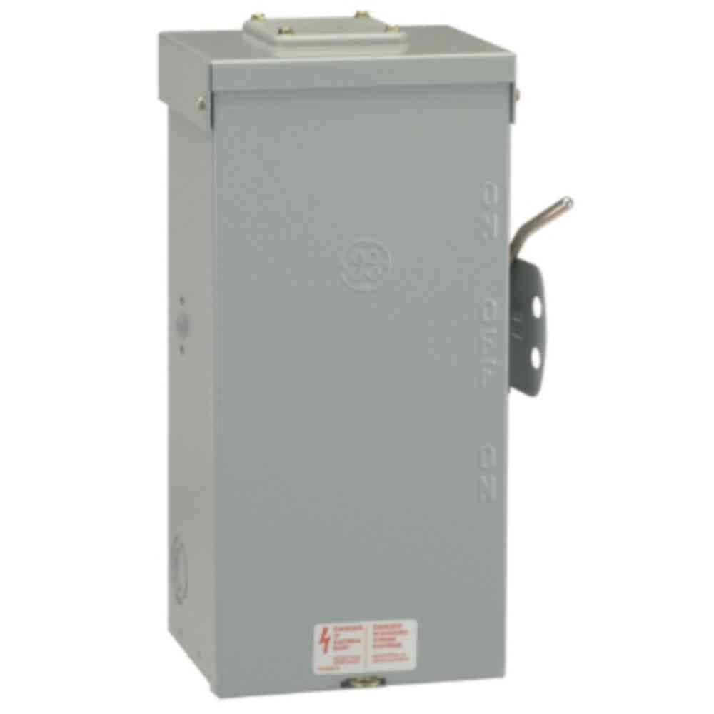
I use this manual transfer switch between grid and my solar to power my critical loads panel
and under $200
GE 100 Amp 240-Volt Non-Fused Emergency Power Transfer Switch TC10323R - The Home Depot
The GE 100 Amp 240-Volt Non-Fused Emergency Power Transfer Switch is great for running your outdoor backup generator. This emergency power transfer switch is designed for use with 12 - 1 AWG/kcmil copper
www.homedepot.com
and under $200
ksmithaz1
Solar / EV Junkie
Nice, I hit mine with a temperature gun while charging the car, pulling around 60 amps a while back. Slightly warmer than ambient, this was of concern to me. To that end I also mounted the DIN rail in a fully covered 12x12 steel box for the primary feed relay, and the 50A feed out to my EV pedestal (Feed wire to the pedestal is actually #4).Just putting this out there, not saying this couldn't happen on an American made product. This is their product that has been on the market longer and has lots of reviews.
This is the review that scared me when i was looking to purchase their unit last year:
https://www.amazon.com/gp/customer-...=cm_cr_getr_d_rvw_ttl?ie=UTF8&ASIN=B07J59ZKTJ
Also interesting as the higher amp units I have are switch left, controls right. The one I have that failed (mechanically not catastrophically) is like the one above, controls left, switch right.

So I went back out just to verify a little bit ago... Fuzzy red dot on case is a reflection from the white side board @89.4


Upper inputs are from the panel on the left. Lower inputs (top) are from the main panel, load wires are underneath. Load was around 8KW, HVAC && HWH running. Highest reading in the box right here at this spot 89.9 about 0.5F differential. Left relay feeds the EV pedestal, and yes I know you are not supposed to band red wire, at the time it was all I had. Right relay is the 100A primary to the panel on the left. I'll take another when the car is charging: I'll run some hot water, when the AC kicks on, but I did this before and didn't see much of anything that was of concern. BTW it's a good idea to hit the breakers in your panel from time to time. I had a brand new SquareD 50A breaker going to the HVAC that was heating up and tripping. Connections were all tight.
I will say that the connections on these things are difficult. You will note the lugs i installed on the top wires, this was to reduce stress on the box. I twisted and fought the crimp connectors on the lower panel feed, to minimize stress from the wire, it can distort the case, and pop it off the DIN rail.
Temperature checks are something I've gotten into a habit of doing since I started messing with panels and UPS's in my computer rooms. Just hit the gun on your twist-loc boxes, breakers and tie points around your ups. Caught more than one failure before it happened. Nailed a bad clothes dryer outlet right here in my house that had a weak contact as well. Doesn't take long.
I like seeing them in a steel box. Good job.Nice, I hit mine with a temperature gun while charging the car, pulling around 60 amps a while back. Slightly warmer than ambient, this was of concern to me. To that end I also mounted the DIN rail in a fully covered 12x12 steel box for the primary feed relay, and the 50A feed out to my EV pedestal (Feed wire to the pedestal is actually #4).
Also interesting as the higher amp units I have are switch left, controls right. The one I have that failed (mechanically not catastrophically) is like the one above, controls left, switch right.
View attachment 173041
So I went back out just to verify a little bit ago... Fuzzy red dot on case is a reflection from the white side board @89.4
View attachment 173043
View attachment 173044
Upper inputs are from the panel on the left. Lower inputs (top) are from the main panel, load wires are underneath. Load was around 8KW, HVAC && HWH running. Highest reading in the box right here at this spot 89.9 about 0.5F differential. Left relay feeds the EV pedestal, and yes I know you are not supposed to band red wire, at the time it was all I had. Right relay is the 100A primary to the panel on the left. I'll take another when the car is charging: I'll run some hot water, when the AC kicks on, but I did this before and didn't see much of anything that was of concern. BTW it's a good idea to hit the breakers in your panel from time to time. I had a brand new SquareD 50A breaker going to the HVAC that was heating up and tripping. Connections were all tight.
I will say that the connections on these things are difficult. You will note the lugs i installed on the top wires, this was to reduce stress on the box. I twisted and fought the crimp connectors on the lower panel feed, to minimize stress from the wire, it can distort the case, and pop it off the DIN rail.
Temperature checks are something I've gotten into a habit of doing since I started messing with panels and UPS's in my computer rooms. Just hit the gun on your twist-loc boxes, breakers and tie points around your ups. Caught more than one failure before it happened. Nailed a bad clothes dryer outlet right here in my house that had a weak contact as well. Doesn't take long.
ksmithaz1
Solar / EV Junkie
Follow-up.I like seeing them in a steel box. Good job.
Load ~14KW, both AIO's making fan noise:
A bit warmer out now:


Meh, no longer the hottest spot.

So 8F hotter at the connection. So running about 60 or so amps right there L1/L2 are +- .1F.
Buuuuuttt. Note the pedestal relay on the left is now on as "Primary" (upper). The white control wire is from a relay in the control computer. There is a feed from the panel to the secondary relay to force it on by default. The breaker from the grid panel (lower top) is off. This is where you see connections and wire-size play a role.

So the 32A draw out to the pedestal from the #6 wire feed from the panel is warmer at the connection than the 60+A draw from the inverters. I shut it down and put a micro-turn on this lug. It dropped it 2F, now matches black below 110F. I'll be replacing the banded white on this, at which point I will swap the screw lugs with copper crimps, but nothing in here is alarming to me. All the plastics are just a few degrees above ambient.
This is why we have the 80% rule. All the #2 is rated at 100A, thus runs much cooler at 65A than the #6 at 32A. No Pic but the #4 feed wire underneath (copper crimp lugs) was running 105F. #6 is 50A so 32A is well below 80% as well. If that were to run up around 50A it would probably hit 130, I don't ever plan on it actually going that high for any length of time, but it could before it trips a breaker. Guys like @timselectric have a lot more experience than I but everytime I've seen a catastrophic failure with something fully wired (Not an outlet, they just go bad with age), it's because a wire was not tight or it was installed improperly and it got very hot under load. Unlike your house where heavy loads turn off an on all the time, I've always worked with equipment that just sucks it down 100% of the time. Run a breaker at 100% for a month or so, you will have problems. Run at 60% with a connection that isn't tight at the equipment release the magic smoke there instead.
Ferrules are supposed to help. Jury is still out on that for me.
Kenny_
Solar Addict
This!I know essentially everything is made in China these days. But I wouldn't trust a generic chinese unit that is not made to US specs. If you value your house, I would go with something like this: https://www.amazon.com/Automatic-Transfer-Switch-Pole-Warranty/dp/B07YCT29C2
Yes it is five times more expensive, and I'd submit, it's probably overpriced, but they have UL spec'd versions that are done to code.
UL listed versions on their website: https://mtspowerproducts.com/produc...ontrols/125a-150a-transfer-switches-2p-3p-4p/
ksmithaz1
Solar / EV Junkie
Only one of their three similar items is UL listed. One of the problems I have with 'Made in America' is it can't be 5 times more expensive. I get all my dental work done in Los Algodones because *after* my deductables and co-pays, it's still less expensive just to pay cash there than the out-of-pocket would be here. That means we have a disconnect somewhere between the service or product being rendered and what is being charged. I might pay up to twice as much it's decidedly more expensive to do things here, but $50 vs $1000? The difference will buy a lot of $100 steel boxes, and I'll toss in a Fire Extinguisher.This!
Back in the day I was talking to a tech at Fry's electronics. We were discussing the number of returns on this one particular inexpensive motherboard (that I was returning/swapping) compared to a similar MSI (which I was considering to replace it with). He said he would say the MSI except he found out just how many of the inexpensive ones they had sold vs the number of MSI's. Turns out as a percentage the return rate on the cheaper product was about 1/2 the more expensive one. He did agree it was more likely someone would return a flakey $200 part vs a flakey $80 part, but no way would it be twice as frequent. I will say however different brands of the "same device" are sometimes not the same.
I also like the idea of the rotary switch. The movement is more fluid, and after examining the inside of one the construction seems robust enough. It also means the actuator coil needs less vampire current to operate. The older / larger stuff I've seen used a slide switch or a contactor type design. The one I have has pretty much flipped at least twice every 24hours since I put it in. It seem to handle steady state loads well over 12KW without any difficulty, and doesn't heat up more than expected. YMMV.

We can clearly see these wires are NOT in a crimp lug. They appear to be thhn or other stranded cable shoved into one side of the terminal and screwed down. I can assure you if one of these was sort of loose and you started pumping 30A thru it, you are asking for it to catch fire. Solid wire would be better for this scenario, but these lugs were not designed for free end stranded wire. Stranded wire should be in an enclosed clamp that compresses from the sides, not slid in next to a screw.
So this makes me suspect everything from that point on because we were stupid. I hope he doesn't go into reloading or gunsmithing.
This is great idea, mounting in a steel box. You're obviously doing your due diligence. Do you have a link to the temperature gun that you're using?Nice, I hit mine with a temperature gun while charging the car, pulling around 60 amps a while back. Slightly warmer than ambient, this was of concern to me. To that end I also mounted the DIN rail in a fully covered 12x12 steel box for the primary feed relay, and the 50A feed out to my EV pedestal (Feed wire to the pedestal is actually #4).
Also interesting as the higher amp units I have are switch left, controls right. The one I have that failed (mechanically not catastrophically) is like the one above, controls left, switch right.
View attachment 173041
So I went back out just to verify a little bit ago... Fuzzy red dot on case is a reflection from the white side board @89.4
View attachment 173043
View attachment 173044
Upper inputs are from the panel on the left. Lower inputs (top) are from the main panel, load wires are underneath. Load was around 8KW, HVAC && HWH running. Highest reading in the box right here at this spot 89.9 about 0.5F differential. Left relay feeds the EV pedestal, and yes I know you are not supposed to band red wire, at the time it was all I had. Right relay is the 100A primary to the panel on the left. I'll take another when the car is charging: I'll run some hot water, when the AC kicks on, but I did this before and didn't see much of anything that was of concern. BTW it's a good idea to hit the breakers in your panel from time to time. I had a brand new SquareD 50A breaker going to the HVAC that was heating up and tripping. Connections were all tight.
I will say that the connections on these things are difficult. You will note the lugs i installed on the top wires, this was to reduce stress on the box. I twisted and fought the crimp connectors on the lower panel feed, to minimize stress from the wire, it can distort the case, and pop it off the DIN rail.
Temperature checks are something I've gotten into a habit of doing since I started messing with panels and UPS's in my computer rooms. Just hit the gun on your twist-loc boxes, breakers and tie points around your ups. Caught more than one failure before it happened. Nailed a bad clothes dryer outlet right here in my house that had a weak contact as well. Doesn't take long.
ksmithaz1
Solar / EV Junkie
Just pick up a cheapo, amazon or harbor freight, $30 or so. We are looking for delta's not precision. ie the number on the screen is not important it's how much it varies under a load. Don't care if it's off 2 degrees, or even other minor mis-calibrations, just needs to be close.This is great idea, mounting in a steel box. You're obviously doing your due diligence. Do you have a link to the temperature gun that you're using?
I use this manual transfer switch between grid and my solar to power my critical loads panel
GE 100 Amp 240-Volt Non-Fused Emergency Power Transfer Switch TC10323R - The Home Depot
The GE 100 Amp 240-Volt Non-Fused Emergency Power Transfer Switch is great for running your outdoor backup generator. This emergency power transfer switch is designed for use with 12 - 1 AWG/kcmil copperwww.homedepot.com
and under $200
How big was the job to get this installed? Looks like you would have to pull grid power into one side?
Is there any concern of using this with generators that are floating neutral (which all portable generators seem to be). reading on the homedepot questions section, someone asked if the switch isolates neutral.
Someone replied:
"No it does not, you would need a three pole switch to do this. However in most all applications it is not necessary to isolate the neutral/grounded conductor. it would be dangerous to isolate the neutral and not ground it properly as the neutral wire is intentionally attached to the service grounded conductor and then attached to the grounding electrode(ground rod) conductor at the service entrance. I am not condoning your thoughts, but be sure you are well aware that a floating neutral wire (one that is not grounded) can create a unintentional hazard in a electrical system."
Not sure what can be done for all these floating neutral generators? I thought it just uses the homes neutral?
dougbert
Solar Addict
How big was the job to get this installed?
see below
Looks like you would have to pull grid power into one side?
grid from the top, solar from bottom and outflow from the center to the Critical Loads Panel
Is there any concern of using this with generators that are floating neutral (which all portable generators seem to be). reading on the homedepot questions section, someone asked if the switch isolates neutral.
Someone replied:
"No it does not, you would need a three pole switch to do this. However in most all applications it is not necessary to isolate the neutral/grounded conductor. it would be dangerous to isolate the neutral and not ground it properly as the neutral wire is intentionally attached to the service grounded conductor and then attached to the grounding electrode(ground rod) conductor at the service entrance. I am not condoning your thoughts, but be sure you are well aware that a floating neutral wire (one that is not grounded) can create a unintentional hazard in a electrical system."
Not sure what can be done for all these floating neutral generators? I thought it just uses the homes neutral?
they do use the homes' neutral
here is the link to the post where I swapped out my 3 pole 60 amp (I am trying to sell that BTW) switch to the ABB/GE 2 pole 100 amp switch

Solar house generator I started DIY back in 2000 - My path from Trace to Xantrex (on FLA battery) to XW Pro inverters on Tesla Model S batteries
Wow I love this XW Pro!!!! As my wife is recovering from the stroke, I am doing most of the cooking. Well today I put a roast in the oven to cook for 3 hours slowly (3500w) Then I turned on the water distiller which is on one of the range back burner for 2.5 hours (2500w) My wife proceeded to...
 diysolarforum.com
posts after that one, show the work I did
I have common neutral and of course common ground in the house system. For my generator circuit, the house's single bonding point in the MAIN Disconnect provides the N-G bonding for the house and the generator. I have removed any N-G bond from the generators, in order to connect to the house
Yet, I have also added a toggle switch to the generators that will enable/disable the N-G switch OR I have a plug that only has the bond within the plug for Neutral and Ground. I plug that into one of the outlets when I need the N-G bond. And that is when the generator runs standalone and not connected to the house - like camping. Also in standalone cases, I pound a ground rod and connect that - only in standalone mode. When connected to the house, it is floating Neutral and the generator relies on the house for N-G bond and a ground rod
Last edited:
Similar threads
- Replies
- 3
- Views
- 326
- Replies
- 1
- Views
- 100
- Replies
- 22
- Views
- 948
- Replies
- 17
- Views
- 767