diy solar

diy solar

3-Phase SMA Sunny Island (15kW) + Sunny TriPower (30kW)

Hedges

I See Electromagnetic Fields!
Joined
Mar 28, 2020
Messages
20,694
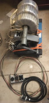
Showing a work-in-progress assembling 3-phase SMA system.
3x SI-5048-US are configured for 3-phase and produce 120/208Y, rated 15 kW continuous.
Sunny TriPower 30000TL-US-10 is 480V delta (or 277/480Y), rated 30 kW.
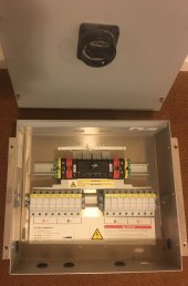
TriPower combiner box will be used, but for now just one string being connected.
Battery bank will need to be upgraded. Starting out with 4x 12V 104Ah SunXTender AGM, 13 years old and 40% of capacity remaining.
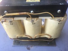
Transformer needed to produce 480V. Three 9kVA toroids wired as auto-transformers, 120V to 260V (close enough to 277V for the TriPower to operate.)
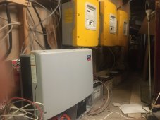
TriPower and SI IMG_2418.JPG

TriPower CombinerIMG_2431.jpg

Transformers 3x9kvAIMG_2669.jpg

All the flying wires are obviously temporary, but good enough for lab work. Will need to be properly in cables or conduit when done. Just getting system functional before placing TriPower and Combiner box outside.

Plugs and sockets for 277/480V 4 wire + ground, and MC3 cables, allow swapping connections. Heavy stuff on dollies so they can be moved easily.

Until firmware of TriPower has been updated, it doesn't have proper UL-1741-SA option. But frequency-watts ramp is present, and just had to expand frequency range to allow that to work while remaining connected to Sunny Island. Shown below at 60.36 Hz, 242W. Sunny Explorer software on an old XP laptop and Speedwire provide control and monitoring. Tried RS-485 adapter with Sunny Web Box but only saw serial number, nothing else. SMA says Sunny Web Box does with with TriPower, so some firmware updates may be needed for that too (or maybe Web Box works through Speedwire? I haven't tried that.)
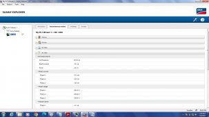
Plant TriPower 6000 curtails with frequency XXX.jpg
 
Although SMA says the TriPower with Sunny Island is for off-grid system only, not for grid-backup, it does work. At least if loaded with lower enough PV wattage to not exceed 56A relay limit in Sunny Island. I wonder if limited-export via SpeedWire could get around that limit.


Because I have 120/240V split-phase service, only the Master Sunny Island connects to grid. For now it is through a dryer cord to 30A breaker, later will use 6 awg for 70A breaker, full 56A 120V input. That's just 6700W, and I'm testing below that for now. All the more reason for limited export.
Sunny Island does have signaling relays which can be programmed to close when on-grid, and I'm contemplating using them to allow split phase 120/240V 56A connection to grid. I would use transformers to make an in-phase (with Master) split-phase out of the two Slave legs that are 120 degrees out of phase with grid.

After experimenting with the toroids I had on hand, going to install a proper UL Listed transformer.
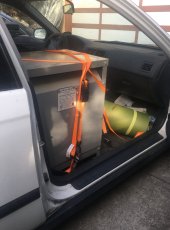
Here's my new 30 kVA 480V Delta to 120/208Y transformer, just arrived home after riding shotgun with me from Southern California.

Riding Shotgun IMG_2736.jpg

Transformers are typically rated about 3% regulation, meaning with 480V in, at no load the output would be 120V +3%, and under full load 120V -3%. Since I'll be operating it backwards, I expect 120V in to produce 480V - 3% no-load, and -9% full load. But that just has to be within spec; then TriPower will deliver power to the 480V side and boost voltage.

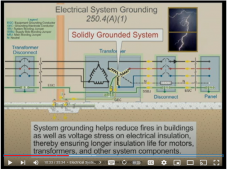
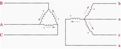
Here's how the transformer was meant to be used:

1663219697065.png

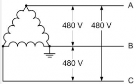
With me driving the 120/208Y side, the 480V delta side isn't referenced to ground. SMA instructions were updated to say that while 480V delta is OK for this model inverter, it is important not to have a sustained fault of one line to ground, which would look like corner-grounded delta. That would drive the other two lines to 480Vrms from ground, likely over-voltage for EMI filter and surge arrestor components.


1663219971596.png

For isolated 240V single-phase source you would just use an auto-transformer to establish neutral, which you then ground. Doesn't work that way with 3-phase. This is an already understood problem, and "zig-zag" transformers provide a solution. Those are three, 2-winding transformers, and two windings from two different transformers are connected in series to form each leg of a "Y". (I still haven't wrapped my head around how it works, but my SPICE simulation says it does. Also says it doesn't carry as much current as is needed to trip a breaker, but reportedly they are able to do so.) So, I've got a zig-zag transformer coming in the mail.

 
Last edited:
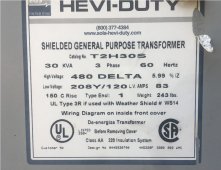
Tried powering up the 3-phase transformer.

Label IMG_2748.jpg

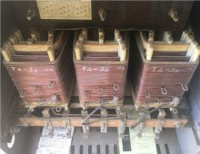
Interesting to see air gap between turns in one direction away from the "E" core. Good cooling. Expect more leakage inductance.
Six taps, haven't seen a table of what voltages (above/below 480V).

Instructions say to remove transportation bolts. I see bolts through rubber pads, but if those were removed there would appear to be nothing securing it at all.

Space between windings IMG_2751.jpg

I'm going to use it to boost from 120/208Y to 480 delta, so I hooked a cord between one 120V leg and neutral.

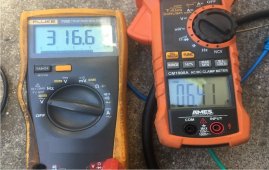
6A noload IMG_2754.jpg

It draws 6.41A on a single phase (800W, hope that's almost all reactive). Secondary only shows 316V.
It buzzed rather loudly.

I then applied 120/208Y (actually 208 delta, used a 3-wire plus ground cord.)

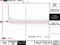
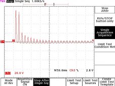
Inrush 120V to 3-phase transformer 091722 1908.jpg

Each time I applied power, transformer inrush varied (depends on phase when turned off, which determines magnetism of core, and phase when turned on; if of same polarity, can saturate.)
The one captured above showed near 80 A(peak), settling to around 12 A(peak). Not looking much like a sine wave. Meter showed 2.84 Arms (each phase) in this configuration. Still buzzed, and will likely cause way more loss than I want. (Also more than the toroids did.)

1A 450V IMG_2772.jpg

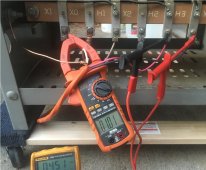
With the three toroids converting 120/208Y to 277/480Y (actually 260/451Y as shown above), the 480V delta primary was driven, and carried 1.01A. It was not as noisy. Still 260W x 3 phases, hopefully mostly reactive.

Inrush 480V to 3-phase transformer 091722 1913.jpg

Inrush into 480V side, 70A? Maybe I put the probe in the wrong place? But steady-state current matches DMM.

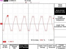
Steady 480V to 3-phase transformer 091722 1916.jpg

Steady state into 480V side shows 1.5 A(peak). Distorted waveform.

I don't think this transformer is going to work to boost voltage from Sunny Island to TriPower. Something about the way it is wound, gets to far into saturation driven in the reverse direction. I cut voltage in half with Variac, to about 60V instead of 120V, and it drew 1.0Arms, was quieter.

And here I just bought it a nice new 600V 15A zigzag transformer, so the 480V Delta could have a neutral connection.

IMG_2749.JPG
 
Googling the topic of using a step-down transformer in reverse (for step-up), I find some mention of issues like higher inrush and turns ratio delivering a different nominal voltage.


"It also is important to note that manufacturer published inrush values are most often descriptive of transformers that are energized from the primary winding, which are the outer windings of a transformer. If the transformer is reverse-fed and energized from the secondary winding—the inner windings—you can expect the inrush values to be dramatically greater. To address this issue, engineers should always be cautious of back feeding in applications above 75 kVA and select the largest OCPD allowed by code."

I had read previously that when one winding is over the other, the outer winding has greater leakage inductance to air, and is usually the primary winding. The air-core portion of inductance isn't affected by core saturation, so remains to limit rate of current rise. Note the large air gap in my photo (of power transformer). The zigzag transformer, in contrast, has windings wrapped tightly on top of each other.

My scope traces did show inrush current greater in proportion to steady-state current when operating the transformer in reverse. In fact, about as high a peak (70A) as when operated forward (80A). Of course, each time measured, inrush will vary at random (unless you control phase of turn-off and turn-on.)

What I'm seeing, that simply driving 120/208Y side at nominal voltage caused considerable saturation and excessive current, doesn't seem to be addressed in web pages I've seen.

The toroid I use behaves better. It was designed for a UPS inverter. Not sure, but likely higher voltage battery driving 240V winding, split-phase taken from two 120V windings. Maybe the non-sinusoidal waveforms I got from it are also due to driving winding intended as secondary.


Possibly a different 480V to 120/208Y transformer would behave better for step-up, but I have to buy it before I can try it.
 
We have a Winner!

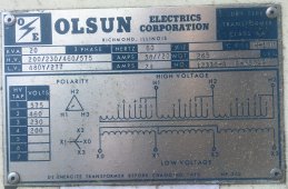
My latest transformer acquisition is a 20kVA Olsun 3-phase isolation transformer:

Label IMG_3356.jpg

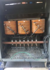
Primary is delta connected, taps for 200/230/460/575V

Secondary is 277/480Y

Delta primary IMG_3355.jpg

That seems like it could meet my need of stepping up from 120/208Y of 3x Sunny Island to 277/480Y for Sunny TriPower. I expect about 4% high output (208V into 200V winding) and the usual higher than ideal current at idle I’ve seen for most transformers.

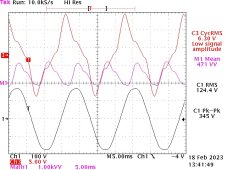
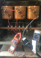
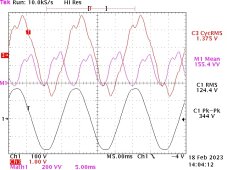
Olson 120-208 into 200 delta 021823 1059.jpg

Sure enough, 6.3Arms drawn from each 120V leg (756 VA combined real and reactive power.)

I think I have the voltage probe on same phase as current, but reverse polarity. Voltage is most negative when current is crossing zero (that would where rate of change is greatest, if current looked like a sine wave.)

Trace M1 Mean is supposed to be real power, point by point product of voltage and current, then averaged. But inverter draw of 0.2kW (vs. 0.1kW normal no-load) is well under 3x 471W.


Next, I used my usual trick: reduce applied voltage. But how to do that while maintaining output voltage? Well, 277V/120V = 2.308, and lookie here! Primary winding taps 460V/200V = 2.3, which is close enough for me!

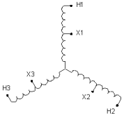
I rewired the primary as WYE, connecting H1, H2, H3 to neutral (green wire of extension cord, supposed to be 120/240 3-wire + ground but I’ve adapted it to a 120/208Y plug at the inverters; I have a separate cord providing ground). The three 200V “HV Tap #4” get three 120V phases (X1-3 in the diagram). The three 460V “HV Tap #2” provide 277V (H1-3 in diagram). Unlabeled middle of diagram is connected to neutral for this next test.

WYE Autotransformer.png
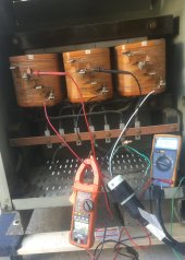
WYE primary IMG_3365.jpg


Current draw is reduced to 1.375A per phase.

For reasons I don’t understand, neutral is carrying about 3x what each line carries (no pictures to show). I swear those are all 120 degrees out of phase!

Olson 120-208 into 200 wye 021823 1122.jpg


Maybe it is something funny about WYE (Sunny Island) driving WYE (transformer). Normally WYE drives delta, or delta drives WYE.

There isn’t supposed to be any current in neutral. What if I disconnect it?

WYE primary neutral open IMG_3368.jpg

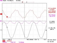
Current no longer registers on the HF clamp meter (It seems to show 0.00 for less than 1.00, but shows fractions above that, when on AC range?)

Olson 120-208 into 200 wye_noNeutral 021823 1137.jpg

Now, no-load current raw is just 313 mA per phase. Sunny Island is down to 0.1kW delivered, can’t resolve below that. I need to double-check with grid disconnected and DC clamp meter on battery cable.

Will a WYE connected transformer work if neutral is disconnected? I think so; the phase vectors should carry current, so long as all windings have identical current. But I thought current was supposed to be zero in neutral, and I got about 4A. Yet, only a couple volts on neutral when open-circuit. I have heard of circulating currents when connecting WYE to WYE.

For my application (3-phase 277/480Y or 480 Delta, balanced power from inverter) I think I can get away with leaving neutral open. I’ll know after I hook up TriPower and feed a few kW through it.

Delta Wye.jpg
 
Last edited:
"37.5 KVA 1 phase Single Phase 240x480 to 120/240"

That's single phase. I need 3-phase for Sunny TriPower

“factory new”

I like that.

"Quantity: 3 available"

With three of them, I could do this. If I feed 120V in (from my WYE connected Sunny Island) and connect the 480V in Delta, that is the voltage I need.
TriPower will accept 480 delta, but that carries the risk if one line shorts to ground, because it was floating, nothing shuts down. Driving the other two lines to 480Vrms from ground will over-voltage the equipment (likely EMI filters and surge arrestors.)

Biggest problem doing this is it involves backfeeding the transformer. Refer to earlier postings showing excessive no-load current draw.
Most commercial transformers (cost optimized) are not reversible. Primary is to be used as primary, and secondary is to be used as secondary.


"Price: US $2,933.00"

I don't like that either. Especially since I would need three.

The 20 kVA I bought cost about $500 delivered.
I missed out on a 30 kVA that might have been ideal, for about $600 + $600 shipping. Lost to another buyer while I tried to find a lower cost carrier.
But driving it at normal voltages, it would probably have drawn higher no-load current than I want. I'm getting better results around half of rated voltage.
Sorry, didn't even notice. I saw 480v and instantly assumed it must be 3 phase.
Where did you buy it for $500 from, if you don't mind me asking?
 
240/480 step-down to 120/240 single phase is quite common. 480V 3-phase might be distributed within a building, and 120/240 made at individual units. Like these:


I got the 20 kVA 3-phase from the following seller. Price was $250 and shipping $300 (I picked up at freight terminal), came to $575 with tax.
He has flat shipping rate of $200 to $300 on many of the transformers. Coming from Michigan, better than quotes I had been getting recently.


There was a 45 kVA 480 delta to 120/208Y for $500 at Alan Steel in Redwood City, which I didn't buy.
I bought a 30 kVA one (described above) for $200 and picked up in San Diego. That's when I found using step-down for step-up didn't work.

I also bought a single phase 240/480 to 120/240 step down for $475 including tax, also picked up in San Diego. That one is 3R and potted, will use outdoors for derived neutral from a separate source. (think sharing backed up power with a neighbor, avoiding connecting neutrals together which would mean ground bond occurring in two locations.)


That shows the dramatic improvement in current waveform driving 240V primary winding with 120V, vs. driving 120V secondary winding with 120V. That has grid as source, and is smoother than my 3-phase waveforms which are driven by inverter, possibly due to Sunny Island having some difficulty with inductive load.

Most of the open frame transformers are NEMA 1, but would be 3R with shields on the upper vents. Good to get as part of the purchase if you need it, otherwise a few are listed separately on eBay.
 
Last edited:
I only skimmed over this. But it's very interesting.
I'll be back this weekend to absorb it fully.
Very cool project.
 
Destined for deployment at my other house.
If PG&E doesn't choke on my NEM request (3-phase 480V inverter for 120/240V split-phase service.)
Or even if they do, only the NEM process is affected by their cooperation. It is already up and running at my present place. If they don't cooperate, I gotta buy a single phase Rule-21 compatible inverter.


I only requested a 3-phase transformer on their pole, fed from 12kV about 200' away. But no, they couldn't give me that for less than 20 times what the transformer itself costs.

Throwing a wire over the fence to a neighbor who happens to be fed by transformer on different leg of 12kV, might be able to get 3rd phase. Could have issues with anti-islanding if not careful; running a motor that way I think it would backfeed, and no UL-1741 in sight.
 
Throwing a wire over the fence to a neighbor who happens to be fed by transformer on different leg of 12kV, might be able to get 3rd phase.
I don't think that would give you an actual 3rd phase. Unless all transformers are connected together on the load side. You might see something, but I don't think it would be usable or consistent.
 
Assume load sides are isolated (except neutral/ground bond, then through earth.)
But a pair of 120/240V circuits 120 degrees apart, one can be transformer isolated to get 240V, then connected L1 to L1 (or L2, as needed) of the other.
That gives 120/240 open-leg high-leg delta.

iu


Scroll down to #18:

 
Instructions say to remove transportation bolts. I see bolts through rubber pads, but if those were removed there would appear to be nothing securing it at all.
Don't remove completely. Just loosen so that the rubber is only compressed by gravity. This removes vibrational noise.
 
Assume load sides are isolated (except neutral/ground bond, then through earth.)
But a pair of 120/240V circuits 120 degrees apart, one can be transformer isolated to get 240V, then connected L1 to L1 (or L2, as needed) of the other.
That gives 120/240 open-leg high-leg delta.

iu


Scroll down to #18:

Yes, as long as you make the linked connection (A).
It should be easy to determine, as it will have zero volts between your service and your neighbors.
And the transformers can only handle 50% of nameplate rating. Which probably won't be a problem with your setup. As long as your neighbors service is not fully loaded.
One thing that I would worry about is the grid conductors coming from two service drops.
Are the two transformers on the same utility pole? Or are they on different utility poles?
 
I'm not seriously considering the open delta at that property.
I tried to get 3-phase service. Guy who came to look estimated $15k. Lady I spoke to later said $150k. So I won't.
That property is fed by a pole pig around the block, and a second pole pig is close by. Maybe it feeds my neighbor, not sure.

My San Jose property, half a dozen of us are fed by underground transformer in my front yard. I hoped that received 3 phase and fanned out different legs to different neighbors, but last PG&E guy I saw standing over it said it was single phase. Maybe I could get another phase from a different neighbor who has pole pig on other side of block.

For 3-phase inverter, this would feed power back through neighbor's meter.
For 3-phase motor, should work. But if one service went down, motor would continue running like an induction motor, and I think push power into the dead circuit.

So my only solution is running three Sunny Island. Mostly so I can use TriPower.
 
Just use a battery charger from your grid. And accept the conversion losses. It's probably the simplest solution. I assume that the grid is just a last resort backup.
Unless you are wanting grid-tied for the property.
Then never mind. lol

Actually if you want to export to the grid. Just add a single-phase hybrid AIO. And then you can export from the battery. And use it for backup through the battery.
 
I've got the Olsun connected as WYE auto transformer, step-up 208 to 480, with neutral unconnected.
I used 4-wire extension cords to connect it. Meant for 120/240 + ground, but I adapted to 120/208Y and 277/480Y plugs and sockets.
(easier to run extension cord than temporarily relocate transformer from where it is stored.)


This did wake up TriPower, but with overcast and the sun low, didn't bother draping "UF" PV extension through the house to my workshop. Will try tomorrow.
TriPower was slow to respond, and never did see it report the AC voltage. Hope it works tomorrow.
 
Grid tied property already. Just applied for NEM 2.0, want 20 years of 100% efficient long-term (annual) net metering energy storage in the utility bill.
I don't want to buy a battery big enough to run all house loads.
I could buy a Sunny Boy 7.7kW -41 model (or two). But I have TriPower and Sunny Island, so trying to install these instead, get 3-phase conversion for garage and backfeed of grid, with small battery backup.

Sunny Island Master is the battery charger from grid. It also allows backfeed through its relay. Everything you see in post #1 (except new transformer), which is already operating. Challenge will be supporting PV greater than current handling of SI Master's relay; can I curtail production while on-grid? Or should I put in big enough battery to buffer it, and disconnect to prevent over-current of relay if battery full?
 
Can you export single phase from your 3 phase setup?
Assuming that the neighbor buddy system doesn't pan out.
 
Back
Top