diy solar

diy solar

(4) 12v wired in Series for 48v Bank

HARG Hunter

Thirsty for Off-Grid Knowledge
Joined
Jul 10, 2020
Messages
210
Location
Iola, Wisconsin
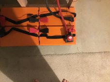
I know how to wire these up to make them a 48v volt bank.
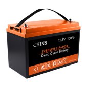
(4) CHINS Lithium 12v 100ah batteries (Photo Attached)

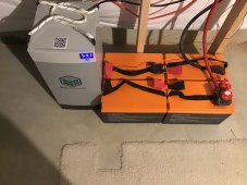
Just looking for photos of anyone/everyone else's similar style bank.
I can stack them on their side or just leave them as is.
I plan on using 2/0 cables.

Anyone want to post a photo of their bank?
I like things to be neat and orderly, so I'm hoping to pick everyone's brain or maybe copy a setup if I like it.

Thanks in advance!
 

Attachments

  • CHINS.jpg
    CHINS.jpg
    103.1 KB · Views: 4
Here you go. I made copper busbars to run between the batteries and added a fuse and disconnect switch at the main positive. The two small red leads are for a victron BMV712 which tracks battery state including midpoint drift

The 4 batteries are not that well matched, and despite repeated efforts they still drift by a full 2% at the top of the voltage curve which for me is 56.2 volts. I have thought about adding a balancer to them but thus far haven’t bothered since the deviation goes away as they settle
 

Attachments

  • C6A63A54-20E8-4CEA-B9CB-6E1F726DDBD3.jpeg
    C6A63A54-20E8-4CEA-B9CB-6E1F726DDBD3.jpeg
    242.1 KB · Views: 47
  • BCB15847-1C56-41B6-8675-0098D4DB755D.jpeg
    BCB15847-1C56-41B6-8675-0098D4DB755D.jpeg
    234.3 KB · Views: 45
Last edited:
Here you go. I made copper busbars to run between the batteries and added a fuse and disconnect switch at the main positive. The two small red leads are for a victron BMV712 which tracks battery state including midpoint drift

The 4 batteries are not that well matched, and despite repeated efforts they still drift by a full 2% at the top of the voltage curve which for me is 56.2 volts. I have thought about adding a balancer to them but thus far haven’t bothered since the deviation goes away as they settle
Exactly what I'm looking for. This is nice and clean. Was thinking on going with bus bars where possible as well.
Are these CHINS or Ampheres?

What did you use for bus bars?
 
Chins batteries. I bought a length of 0.125" x 0.75" Copper Rectangle Bar 110-H02 from online metals and drilled my own bus bars
 
Last edited:
Actually what I planned as well. Shrink wrap over the exposed copper it looks like?
Yep, but I don’t think shrink wrap is the right term, but I’ve not had enough coffee yet to correct it, and yeah, that’s the idea it’s an insulator. The terminal covers come from auto zone. The fuse holder is from blue sea systems and carries a 75 amp fuse, the disconnect switch is also from blue sea systems if I recall

Blue Sea Systems MRBF Surface and Terminal Mount Fuse Blocks.​

Heat-Shrink / I have a bunch.
Thanks for the heads up on everything!
 
2% of what?

Voltage? .002 x 56.2V = .1124V though i cannot imagine this being a meaningful number.
Yes, voltage, now I haven’t been in school for a bit, but I thought a pct was 1/100 vs 1/1000 and 1.124 volts does raise my interest. This is the midpoint difference, that is delta at the 24 volt split, not at a given battery, but still it is worth monitoring. I need to measure the voltages at each battery when theyre at the top. I did it once, but I cannot remember the exact numbers. I do remember that battery 1 was the highest by far, and battery 4 the lowest With 2, 3, and 4 pretty close. 2 and3 were very close
 
Last edited:
Yes, voltage, now I haven’t been in school for a bit, but I thought a pct was 1/100 vs 1/1000 and 1.124 volts does raise my interest.
Oops, thanks, you are correct. 2% is .02

Despite my misplaced decimal, i was hoping to bring light to the problem with using voltage or % of voltage (which is non-linear) versus SoC which is linear.

TL;DR warning:

56.2V x .02 = 1.124V
LFP Voltage Chart.jpg
56.2V - 1.124V = 55.08V
At the top of the SoC spectrum 1.1V is the difference between (very roughly) 99.8% Soc vs 98% Soc.

In the middle, say at 3.35Vpc (53.6V battery), the 2% difference (53.6V x .02 = 1.07V) is 52.58V
This represents an Soc difference (roughly eyeballing the chart), 85% Soc vs 60% SoC.

The flatness of the voltage vs SoC curve in the mid-voltages makes a voltage (or % of voltage) much less useful. That was the point i was trying to make but was obscured by my misplaced decimal point.
 
Oops, thanks, you are correct. 2% is .02

Despite my misplaced decimal, i was hoping to bring light to the problem with using voltage or % of voltage (which is non-linear) versus SoC which is linear.

TL;DR warning:

56.2V x .02 = 1.124V
View attachment 79822
56.2V - 1.124V = 55.08V
At the top of the SoC spectrum 1.1V is the difference between (very roughly) 99.8% Soc vs 98% Soc.

In the middle, say at 3.35Vpc (53.6V battery), the 2% difference (53.6V x .02 = 1.07V) is 52.58V
This represents an Soc difference (roughly eyeballing the chart), 85% Soc vs 60% SoC.

The flatness of the voltage vs SoC curve in the mid-voltages makes a voltage (or % of voltage) much less useful. That was the point i was trying to make but was obscured by my misplaced decimal point.
my concern is that the runner pops up over 3.65 x 4 =14.6 (due to a cell in that battery being a runner) volts and trips that battery’s BMS taking down the set. I set 56.2 as my max to provide leeway, but still….
 
So I did a top-up and the voltages were
b1 14.88 main pos. 3.72 per cell. Whoopsie
b2 13.86. 3.47
b3 13.81 3.45. 99.5% SOC by V and more than adequate
b4 13.80 main neg. 3.45

so here’s a question. Is the position in series the cause for the imbalance? I noted that battery had a higher IR when it was delivered, so I think it is just the battery, but I don’t know enough to discount position

anyway I clipped a balancer on them, and think I will leave it. The losses are outweighed by the benefit to my way of doing the calculations of harm vs potential harm

i May also drop my voltage cap to 56.0.
 
Apologies to HARG Hunter for trampling on his thread. Hopefully its run its course for him.
Is the position in series the cause for the imbalance?
Each battery should get the same volts and amps if wired properly (in series or in parallel).

b1 14.88 main pos. 3.72 per cell. Whoopsie
How does the BMS allow this? This is very troubling. Is the BMS smart and configurable?
 
Apologies to HARG Hunter for trampling on his thread. Hopefully its run its course for him.

Each battery should get the same volts and amps if wired properly (in series or in parallel).


How does the BMS allow this? This is very troubling. Is the BMS smart and configurable?
On a CHINs? That was funny. No, these are bottom of the curve 12 volt drop Ins. No BMS access, no Low temp sensors, nada. Wired properly in series is hard not to achieve ?. I think the issues comes down to the IR of battery 1 being higher at 14 than the other tree which were all at 7 to 8 milliohms, but again I am no engineer

in parallel you can make sure all batteries get the same current and voltage at the terminals, but each battery will make use of them differently. Notebthe BB Husky next to the chins, while the cabling to that is the same gauge, same length, same resistance as the cables to the Chins it charges and discharges differently

i always had a hard time keeping AGM batteries in perfect sync too, which is why I had a balancer handy, and why I now just buy 48 volt batteries.
 
Last edited:
Wired properly in series is hard not to achieve
Agreed, your setup looks clear but it is completely covered (nicely).

the IR of battery 1 being higher at 14 than the other tree which were all at 78 milliohms
Yea, there is another thread with mismatched IR batteries misbehaving. Not sure if there is a cure other than adding some artificial resistance to equalize the batteries. Maybe start a thread with a title asking about IR compensation between batteries?


Agreed, your setup looks clear but it is completely covered (nicely).


Yea, there is another thread with mismatched IR batteries misbehaving. Not sure if there is a cure other than adding some artificial resistance to equalize the batteries. Maybe start a thread with a title asking about IR compensation between batteries?


I am too clumsy to ever leave conductive materials exposed, but they are simply 3 equal length width depth drilled 120 copper Which was sanded I didnt “dress the terminals” but with these batteries and my sub 75amp setup I deemed it overkill
 
Apologies to HARG Hunter for trampling on his thread. Hopefully its run its course for him.
No apologies necessary. This is exactly what these types of threads are for.
Watching this conversation may help me avoid pitfalls etc...

I am watching intently.

I had a similar situation with my AGM bank at the cabin. Had to reconfigure the setup to get them balanced better.
 
Back
Top