diy solar

diy solar

600V 20A C/B for my solar string to my MPPT -one pole or 2 pole?

AlaskanNoob

Solar Enthusiast
Joined
Feb 20, 2021
Messages
907
I had the impression that DC only required the positive to be wired into the C/B but a guy we hired as a consultant tells us that with voltage that high, we should use a 2 pole C/B and wire positive and negative through it.

Of course we bought 7 single pole ones already for our 7 strings of panels....

Is it safer to have both poles going through the breaker?
 
If negative was grounded then one pole makes sense.
I prefer 2-pole disconnect before working on it. Especially if non-grounded array.
You can interrupt current flow with one pole, then disconnect MC cables for both positive and negative.
Codes might require 2-pole disconnect.
 
Not a voltage issue AFAIK.

Typically you don't use overcurrent protection on solar array wiring because you size it for Isc x 1.56. However you are required by NEC to be able to open up both poles if neither is grounded which if you are using an MPPT SCC neither will be. If you are using CB as a disconnect then it needs to be 2 pole.
Yes, the plan is to use the C/Bs as the disconnect to shut off a string for maintenance or whatever down the line.

I was under the impression our entire system was going to be grounded from the solar panels, running a ground wire through the trench into the solar shed, connecting all the components and batteries, and then running down the trench through the AC wires to the cabin. But I don't know anything about grounding.

But your comment about it not being grounded because we're using two MPPTs made me curious so I looked at the MPPT and I don't see any ground connection there. Grounding is a mystery to me. Like absolute magic. Hopefully not black magic when I actually starting putting power on these things based on combining my poor reading comprehension to anonymous forum posts...

I'm sold on 2 pole DC C/Bs then. Thanks much folks.
 
Two different applications of grounding. You ground the PV frames with wire back to inverter. You don't ground the PV wires.

All equipment chassis, PV panel frames, AC outlets in the house should be grounded. Wired together, connected to a ground rod, to metal pipes and reinforcing steel/bolts of foundation. That ensures anything you touch doesn't give you a shock.

Then, there is grounding of current-carrying electrical conductors.
Old 6V cars used to have battery positive "grounded" to frame of the vehicle. Today, negative is connected to the frame instead (avoids enhancing corrosion.)

House wiring, the white "neutral" conductor is bonded to ground wires at just one point, typically utility service entrance or where main breaker is located.
PV arrays in the past had negative lead grounded. For some, PV+ was close to +600VDC. Some brands/models, it was better that positive be grounded and PV- was close to -600VDC.
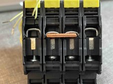
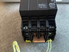
Often, this grounding of PV+ or PV- was done through a 1A fuse or breaker. A short anywhere else blows the fuse, voltage appears on the wire, and inverter shuts off. "Ground Fault" detection.

Common these days is ungrounded PV array. The frames are still grounded, but neither PV+ nor PV- is grounded. This is done due to how high frequency MPPT is designed. For grid-tie inverters, PV+ is around the highest positive voltage of AC wires and PV- is around the most negative AC wires.
 
Of course we bought 7 single pole ones already for our 7 strings of panels....

What is Voc from the array?
Did you find a DC rated breaker where single pole can handle that voltage? Many are only good up to about 150V.
 
What is Voc from the array?
Did you find a DC rated breaker where single pole can handle that voltage? Many are only good up to about 150V.
394 VOC per string.

We have 7 x MNEPV20-600RT breakers. But they are polarity sensitive. They're supposed to be coming out with a new model soon, been saying that for at least the last six months. But if I can some of the polarity insensitive two-pole ones, I'll use those.
 
That isn't a 1-pole breaker, it is a 4-pole breaker pre-wired all in series. Each pole is good for 150V.


For an ungrounded array, I would use 2 poles to interrupt PV+, 2 poles to interrupt PV-
 
That isn't a 1-pole breaker, it is a 4-pole breaker pre-wired all in series. Each pole is good for 150V.


For an ungrounded array, I would use 2 poles to interrupt PV+, 2 poles to interrupt PV-
I think it has been wired up to be one pole though. At least that's what the shop that sold them to me said. I dunno though.
 

Attachments

  • breaker1.jpg
    breaker1.jpg
    236.8 KB · Views: 4
  • breaker2.jpg
    breaker2.jpg
    307.3 KB · Views: 4
Yes, it is wired to act as a single-pole disconnect.
I would remove that middle jumper, connect PV to the outer two terminals, connect MPPT to inner two.
That way when switched off, PV array is completely isolated from inverter.

I could come up with ways to introduce multiple faults so 2 poles (good for 300V) would see 600V and probably not interrupt successfully, rather burn up.

My ungrounded transformerless GT PV inverter had positive and negative each wired through a 1000V fuse. Being fuses of course, only one would blow so it has to handle full voltage.
I'm not sure if NEC requires each end to have breaker or disconnect separately rated for entire voltage even when poles are ganged together.
 
I'm not sure if NEC requires each end to have breaker or disconnect separately rated for entire voltage even when poles are ganged together.
That's a really good question, although I would think it is UL rather than NEC.

I know the Westinghouse/Cutler Hammer engineer's reference book used to show the mechanics of a series connection for DC breakers under different scenarios. Memory is a bit fuzzy going back then, but I think they even had a 1+3 configuration recommendation for some modes, where one pole would be used for a + or -, and the other 3 for the opposite end. This shifted the load-break function to one side and the other side became just an isolator. No idea though what the best way to safely adapt it today is though.
 
These 4 pole IMO's will let you disconnect 4 poles (two strings each). Personally I think their enclosure is laughably cheesy but it's about all I know of that will do the job until you start getting into industrial switches.

Hopefully someone can steer you towards a breaker that suits you because I'd like to know as well.

If you really want to use OCP on your PV strings you could also mount IMO's upstream of touch safe fuses in a Midnite PV box since the touch safe fuses are not load break rated.

Fixed dangerous typo
 
Last edited:
Only in the sense that once you are over 60V both ungrounded conductors need to be simultaneously broken (Per NEC requirements).
It might even be 50. I was leaving the lower voltage out in an attempt to keep my answer succinct based on a pretty safe assumption they weren't down in that range but you're certainly correct.
 
These 4 pole IMO's will let you disconnect 4 poles (two strings each). Personally I think their enclosure is laughably cheesy but it's about all I know of that will do the job until you start getting into industrial switches.
I'm using that disconnect with my system. I'm using just one string (two poles), but have made allowances in case I add another array, which would probably be one large string. I'm putting mine near the inverter, not at the array.

I understand IMO makes these type disco's in 6 or 8 pole versions?

I noticed they're $10 more than they were when I bought mine back in October from SS. Sigh, inflation..
 
These 4 pole IMO's will let you disconnect 4 poles (two strings each). Personally I think their enclosure is laughably cheesy but it's about all I know of that will do the job until you start getting into industrial switches.

Hopefully someone can steer you towards a breaker that suits you because I'd like to know as well.

If you really want to use OCP on your PV strings you could also mount IMO's upstream of touch safe fuses in a Midnite PV box since the touch safe fuses are load break rated.

Thanks for that isolator recommend: https://signaturesolar.com/dc-disconnect-rooftop-isolator-switch-by-imo/

So they are two pole (positive and negative) and I can put two solar strings into each one? That seems like a great idea and I might use these instead of the MNEP circuit breakers.

I have some inline fuses that the consultant we hired said weren't needed, but if we go with these IMOs I think I'll just put an inline fuse in each positive line and use these as disconnects and call it good.
 
So they are two pole (positive and negative) and I can put two solar strings into each one? That seems like a great idea and I might use these instead of the MNEP circuit breakers.
They are rated for voltage and current as to how many poles are required. From memory, I think one pole switching can handle 14A below 500VDC, but check! As long as you are under that level you have four poles to work with. At higher voltages/currents multiple poles need to be placed in series.
 
Of course there is a difference between interrupting current and isolating voltage.
So requirement is different if you want to open this switch with current flowing. But so long as that is possible, best if the switch can handle it (even if not for as many cycles.)

For my grid-tie inverters, instructions are it is better to open AC breaker first, before opening DC switch.
For some equipment (hybrid or AIO) that would not be so convenient.

Best to use 2 poles of that switch for PV+ & PV-, so completely disconnected. What current rating in that case?
Be sure to measure and confirm no voltage remaining on PV input of SCC before touching, may take a few minutes to bleed off.

Because voltage (Vmp) remains on capacitors, I think Voc - Vmp is all the switch has to open. Except in the case of a short, like polarity reversed.
 
They are rated for voltage and current as to how many poles are required. From memory, I think one pole switching can handle 14A below 500VDC, but check! As long as you are under that level you have four poles to work with. At higher voltages/currents multiple poles need to be placed in series.
Awesome, got two of them the other day. Will plan on using just one per string for now. Will double them up later when we expand our solar.
 
Back
Top