diy solar

diy solar

Adding EG4 To Victron/BB - Will this work!?

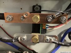
As Adam said, that's too many. Here's how I connected two batteries to the shunt. This was my first try. I subsequently went back and replaced the 3/4"x1/4" copper with 1"x3/8" so that the copper would have more contact surface with the shunt. The other side of the shunt got upgraded too.

View attachment 165488
I do this … bussbars make life easier, more serviceable and connections better and run cooler.
 
Do you have to tap the homemade copper busbar or just drill a hole the size of the connection and screw it on?
 
Do you have to tap the homemade copper busbar or just drill a hole the size of the connection and screw it on?
You can tap or use a bolt. Whatever works for you. Top is 1/4" X 1" copper. Bottom is commercially made link bar that I modified, from here, https://shop.pkys.com/Link-Bars_c_699.html
VERY IMPORTANT!! If you drill holes in a bus bar make sure the surface is dead flat ... no burrs or raised edges.
D33A1AFC-470C-4F7F-AEF0-9CAAABB8753A.jpeg
 
Last edited:
I'm going to connect the 4 BB 2/0 neg cables and the 4/0 EG4 neg cable to a bus bar, then a copper busbar like those from the neg busbar to the shunt. Should be very fancy
 
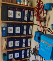
For cable lengths, it's kind of tricky. As you can see in the photo below, the BBs are hooked to the red switches using 2/0 cable and then more 2/0 cable to the busbar.

The EG4 batteries are going to have 2/0 cable from each battery to the rack busbar, and then 4/0 cable from the rack busbars to these busbars in the photo.

How can I possibly match the exact cable lengths of the BBs and the EG4s?

1693569580941.png
 
I do this … bussbars make life easier, more serviceable and connections better and run coole
Do you have to tap the homemade copper busbar or just drill a hole the size of the connection and screw it on?
I have drilled few zillion holes in metals.. iron ..Al- u - minium… SS steel …brass ….copper…gold …silver..platinum…what I do is hit it with a punch ….oil up a SMALL sharp bit.. drill slow and with pressure to create a small pilot hole..
use the next size up bit and do the same….and so on..and so on… always slow with a stout pressure.if you are using a drill press that’s great, but if not learn to do it by hand with a portable drill…
clean holes , no walking of the bitt..no burned up bitts.
simple…
J.
 
With matching the cable length, from my understanding is it’s the combined length of the positive and negative. Usually it’s just easier to match the lengths of the positive to positive and negative to negative. As long as the combined cable length to the new server rack bank match the combined length of the cables to your BB batteries, you should be fine.

Hope that makes sense.
 
I think where DrZ123 is running into a problem is the use of 2/0 and 4/0 on the EG4 side and only 2/0 on the Battleborn side.
 
Any possible issues getting a matched hardware revision so the 2nd Quattro matches the first? I think that's required when linking two or more together?
 
I think where DrZ123 is running into a problem is the use of 2/0 and 4/0 on the EG4 side and only 2/0 on the Battleborn side.
Correct the BB side has 2/0 about 5 feet total length from each 4s bank to the first red switches, then another foot or so to the busbar.

The EG4 will have the small jumpers to the rack busbar in 2/0, and then 4/0 cables from the rack busbar to the main busbar where the BBs connect.

How do I mitigate those cable lengths?
From my understanding, because the server rack batteries are so short, you don’t have to worry too much about losses. You would just want to match the cable length from the rack bus bar back to the bus bar where the BB batteries connect.
 
I think the idea of using equal length conductors and matching battery banks is all about keeping resistance equal so the system uses all batteries equally. Since you want to use different types of batteries I think things are different for you.

I guess you could measure resistances through each bank and see if you can get them close? Does it matter? I would probably use the largest and shortest cables I could and monitor to see how it goes.
 
The EG4 will have 4/0 cables from the server rack w 4 EG4 Lifepower4s to the busbars.

The BBs are wired with 2/0 cables to the bus bar from each 4s block

Is that going to be an issue as well?

Also, can I daisy chain the EG4 batteries with the supplied cables in parallel to the terminals and then just run 4/0 cables from the end pos and opposite end neg to my system? This would be temp until my rack arrives. Or must I use busbars?

Also, can the batteries be used without the RS485 cables connecting them? Mine are on order but don't have them yet
 
The EG4 will have 4/0 cables from the server rack w 4 EG4 Lifepower4s to the busbars.

The BBs are wired with 2/0 cables to the bus bar from each 4s block

Is that going to be an issue as well?
No. The 4S block is 100ah and the battery rack has up to 600ah of power.
Also, can I daisy chain the EG4 batteries with the supplied cables in parallel to the terminals and then just run 4/0 cables from the end pos and opposite end neg to my system? This would be temp until my rack arrives. Or must I use busbars?
You can. I can’t remember, do the battery’s have multiple positive and negative terminals on each battery? I might do it as long as it’s temporary. Keep an eye out for hot terminals as that would show a poor connection.

Also, can the batteries be used without the RS485 cables connecting them? Mine are on order but don't have them yet
Yes. It’s called “open loop communication”. I’m guessing that’s how your BB batteries are running right now. In fact since your mixing batteries, you’ll provably always have to run that way.
 
Thanks! Can I use Rs485 cables to the EG4 communication hub so I can see the battery status but not hook the hub up to the Victron?
 
Thanks! Can I use Rs485 cables to the EG4 communication hub so I can see the battery status but not hook the hub up to the Victron?
Yeah, I don’t know of any reason you couldn’t just use that as a stand alone interface to the batteries.
 
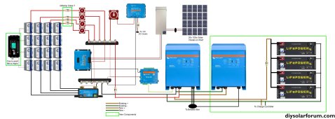
Ok here is my plan for this weekends hookup. I finally got everything I need to at least hook things up temporarily until the EG4 rack comes in a month.

First I'm going to charge each of the 48v 100ah EG4s to the exact same voltage.

Then I'm going to make sure each BB 48v 4s bank is charged to that same voltage.

Then I'm going to wire each of the 4 EG4 Lifepower4s to 2 busbars using the supplied 1ft 6awg cables. One pos and one neg busbar.

Then I'm going to wire the busbars for the EG4s to the busbars currently in the system using 72in 4/0 cables. I will likely put a 48v switch on the POS cable
https://a.co/d/19oLNUO

Then I'm going to turn the switch for the EG4s to on and I should have double the capacity.

Anyone have any concerns here?Layout Diagram.jpg
 
Last edited:
Most people with server racks end up putting a class-t fuse on the positive connection off the rack. Also you’ll want to have one of the 4/0 cables coming from the top of the bus bar and the other one coming off the bottom off the bus bar, that way you have even power distribution across all packs.

Looks like the switch you linked to is some kind of generator.

One recommendation I have is to always test your voltages and polarity with a meter before you turn anything on or make a connection. Never hurts to retest. Can save you thousands…
 
Weird glitch. Fixed the link now

I do have a fuse before the inverter. I was planning on fusing the BBs and this battery bank at a later date

5x Class T fuses are $$$ and there is already one before the inverter. Is adding the fuse before the switch a good idea?
 
I might look at adding the fuse to the rack at least. Your adding a lot of potential current coming off that server rack.

Not sure it matters if you add the fuse before or after the switch.
 

diy solar

diy solar
Back
Top