diy solar

diy solar

AIO High Frequency Invertors. Warning They don't Have An Iron Core Copper Wound Output Transformer.

There was a time when the chopping speed of inverters caused issues with motors in industry.
The jagged wave forms caused voltage spikes and the motors had to be inverter rated, and considerations had to be made around cable terminations because of the spikes... ( radio guys will be familiar with reflected wave stuff )

Higher chopping speeds and better electronics reduced these problems.
I cant remember the last time I installed a drive that needed like and load reactors to protect the motors and insulation.
I bring this up because its the same technology...

I don't think you need to worry about this stuff today in brand name quality inverters for home use.

Fly wheel action and carry through power by transformers?
I hear that said from time to time in my circles but I don't think its really a thing unless your talking about a fero resonant power conditioning transformers and that is not applicable to this.

Bad old days...
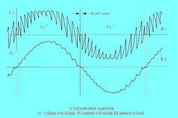
Cycloconverter output was very jagged and the spikes at the end of particularly long cable runs could burn insulation.
1716561986752.jpeg

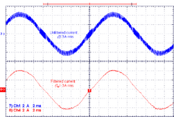
Look at how much nicer the current flow is in a modern IGBT drive.
This image says filtered..
Might have some output reactors on it, article is not specific
1716562052711.png
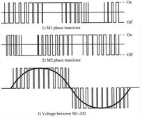
A cheap inverter without the caps and reactors required to make clean AC wll have an output that looks like this.
1716562220485.jpeg
 
Last edited:
There was a time when the chopping speed of inverters caused issues with motors in industry.
The jagged wave forms caused voltage spikes and the motors had to be inverter rated, and considerations had to be made around cable terminations because of the spikes... ( radio guys will be familiar with reflected wave stuff )

Higher chopping speeds and better electronics reduced these problems.
I cant remember the last time I installed a drive that needed like and load reactors to protect the motors and insulation.
I bring this up because its the same technology...

I don't think you need to worry about this stuff today in brand name quality inverters for home use.

Fly wheel action and carry through power by transformers?
I hear that said from time to time in my circles but I don't think its really a thing unless your talking about a fero resonant power conditioning transformers and that is not applicable to this.
The "flywheel" affect is just one aspect and I agree, they are making the HF inverters pretty well driven now a days.

Still, I will take a pass on HF inverters. Maybe for a random use but for my home, I don't see any advantage. I want my gear robust and HF is not that type of design. Sorry to be so forth coming with truth.
 
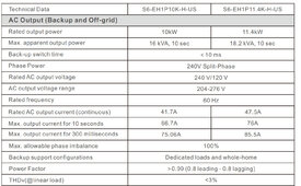
Current generation of high voltage hybrids have none of the issues this thread was started with, for example I'm now using the Solis S6 and it has grid replacement type surge values as shown below. For ~5K street price for a PAIR of the 11.4Kw units I have 22Kw continuous , 35Kw for 10 seconds and 40Kw for 300 milliseconds can start anything. Most installations would be fine with one, but for the price of 2 I have full redundancy and still its close to half the cost of a Sol-Ark or 18kpv allot of posts are using.
 

Attachments

  • 5-24-2024 10-49-06 AM.jpg
    5-24-2024 10-49-06 AM.jpg
    295.9 KB · Views: 11
  • Like
Reactions: DPC
Current generation of high voltage hybrids have none of the issues this thread was started with, for example I'm now using the Solis S6 and it has grid replacement type surge values as shown below. For ~5K street price for a PAIR of the 11.4Kw units I have 22Kw continuous , 35Kw for 10 seconds and 40Kw for 300 milliseconds can start anything. Most installations would be fine with one, but for the price of 2 I have full redundancy and still its close to half the cost of a Sol-Ark or 18kpv allot of posts are using.
Thats amazing. I still would not buy an inverter without transformer isolation. Just can't do it. Sorry. I want a well built truck not a Ferrari.
 
I believe the FETs are at around 180v DC to get your 120v wave form with over head included. They drive the wave form directly so no, there is NO isolation. Pull up a typical HF diagram and you will see with your own eyes.

So, one shorted FET and you have 180v DC on your home mains. This is not to say the a transformer inverter is perfectly safe with isolation, you will still get something bad out with a shorted FET on an LF inverter, just not as direct.

Good thing those Chinese folks make reliable gear so we can trust in the protection circuits.....lol
Have you seen or heard of this actually happening? I haven't been in the industry longer than a couple years so I have not experienced it, but I've never even heard of it happening.
 
Have you seen or heard of this actually happening? I haven't been in the industry longer than a couple years so I have not experienced it, but I've never even heard of it happening.
More then likely and "open" FET is the case. Thats just the common failure mechanism in general. I have heard rebuilders that have seen shorted but they see a much higher volume.

There is more to consider then just a shorted FET. I look at the overall picture. I think a transformer outputed inverter is a MUCH better design. Hands down. Then again, I look for the simple and would not buy a complicated car with all the bells and whistles to fail.
 
I don't see how that's possible. Maybe for one half cycle (8.3mS) but definitely not seconds.
This is very true! The FETs on either system still have the pedal to the metal but its that sharp spike that is really hard on electronics. There is SOME extra kick with a transformer that is not there is pure direct FET switching. The transformer "lag" also prevents less shorted load through the FETs do to it being, well an isolation via air gap.

What electronics love going to "way overload" even for a fraction of a second? Tons of loads is hard on any type of inverter for sure over time!

If you have an HF that can handle an initial spike surge that is way over rated then continues, there is two possibilities;

1 - The inverter is underrated on paper
2 - The FETs take that initial spike, then down slope from there.
3 - Manufacture is using magical "super" FETs

In an LF, the transformer takes the first hit and the FETs are floored during the rest of the "event"

Like I said, its a "HOT" topic.
 
I don't see how that's possible. Maybe for one half cycle (8.3mS) but definitely not seconds.
LF inverters I know are directly powered by batteries, this plus the larger quantity of bulk capacitors in some LF inverters will probably extend surge capability.
 
Like I said, its a "HOT" topic.
Yea a topic full of folklore tales akin to don't put lead acid batts on concrete. HF inverter has output filter that removes that sharp spike. Even during short circuit there will be delay until current flows in transistors due to output filter's inductance.
 
Yea a topic full of folklore tales akin to don't put lead acid batts on concrete. HF inverter has output filter that removes that sharp spike. Even during short circuit there will be delay until current flows in transistors due to output filter's inductance.
Well I think I pointed out some pretty good things, let me know if anything that I said is not true and I will correct it.

HFs are pretty good now a days but I don't see the point personally. Still not going that route,....ever.
 
If you want a low frequency inverter with a transformer that will handle large inductive loads and last a very long time, install an Outback Radian system. Rock solid.
 
I don't see how that's possible. Maybe for one half cycle (8.3mS) but definitely not seconds.
The magic transformer does exist..

And it can provide ride through a brown out even bridge a cycles of power interruption.
But I'm just splitting hairs and showing how really old I am by knowing this stuff...

 
I don't see how that's possible. Maybe for one half cycle (8.3mS) but definitely not seconds.

Not even that long.
I once thought it could do that with energy stored in the inductor.
But the inductor starts to saturate with just no-load current, a couple percent of full rated current.
It can store a little bit more than 2% of rated power for one phase.

I've tested transformers with excess applied voltage, driving them into saturation to get the BH curve.
And with a DC step to RMS voltage rating; in that test they held off current for a bit longer than a phase.
Supply turned off then back on same polarity, about 2 milliseconds before current shot up (that's the "inrush" issue with transformers.)
Reverse polarity and got one time of about a phase before saturation occurs. Next time same polarity I got 2 milliseconds again.

A "Line Tamer" ferro-resonant transformer as mentioned above stores power. But it is closer to 200 pounds for 400VA, much more iron than a typical isolation transformer.

The same mass on a flywheel would store much more.
 
What electronics love going to "way overload" even for a fraction of a second? Tons of loads is hard on any type of inverter for sure over time!

If you have an HF that can handle an initial spike surge that is way over rated then continues, there is two possibilities;

1 - The inverter is underrated on paper
2 - The FETs take that initial spike, then down slope from there.
3 - Manufacture is using magical "super" FETs

In an LF, the transformer takes the first hit and the FETs are floored during the rest of the "event"

Like I said, its a "HOT" topic.

Midnight Rosie is such an HF inverter. Designed by the guys who gave you Trace, one of the few actual LF sine wave inverters. (Warpverter is a DIY version of same architecture.)

Rosie is an 8kW inverter with 16kW 60 second surge (20kW according to some claims.)

Obviously it has FETs and inductors able to process that much power, probably heat sinking limits it to 8kW.


One could use HF isolation transformer to ensure no galvanic path from battery to AC output.
If H-bridge operated wrong or shorted, it might deliver DC to load. But only if HF switching circuit still operating, meaning it can be disabled to shut down rather than continue supplying DC.

Any HF 48V to 120/240V inverter likely has an inherent isolation preventing DC of battery from reaching loads.
HF HV battery inverter might support such faults. Transformerless PV inverters may have such a path from PV string to grid transformers. But if they support wide range of PV (not just > Vpeak of AC) I think they're isolated.

Buck architecture SCC are know to pass PV Voc to battery, blowing out BMS and over-charging lithium cells.
Some SCC like Midnight Classic are HF transformer isolated (on PV+ side only, not PV- side) and don't support that failure mode.
 
The Inductive reactance of the output transformer in an LF inverter does remove some stress on the FETs and other components. By initially opposing an increase in current flow the inverters other components are given time to react to the increased load.

Inductive reactance is the name given to the opposition to a changing current flow. This impedance is measured in ohms, just like resistance.

Inductive reactance is the opposition that an inductor offers to alternating current due to its phase-shifted storage and release of energy in its magnetic field. Reactance is symbolized by the capital letter “X” and is measured in ohms just like resistance (R).


But if you use it wrong, that Inductive Reactance will turn around and bite the FET in the @$$
 
Back
Top