diy solar

diy solar

DIY All-In-One Solar Generator - Control Board

Bhupinder

New Member
Joined
Nov 19, 2019
Messages
113
I've been working on a DIY mobile all-in-one solar generator system since some time.
Must of the hardware has gone into the enclosure and is functional in a very basic sense.
However, integrating multiple generic modules to work together seems more like a Frankenstein's blueprint.

While I am not from Electrical/ Electronics background, but with support from ever helpful forum members planning to substitute
all for a single control board.How and what all gets added remains to be seen as this thing progresses but for starters Idea is to have:

1) Ability to Isolate PV panels from SCC. This is helpful for following reasons:

a) My SCC fuses out from PV current in case batteries are not already in place.
PV panels isolated by default ensure that they are allowed to attach and charge the system only when it is ready to do so.
b) Disconnecting PV panels when system is inactive/ batteries are already charged - may reduce component stress/wear arising
from surplus bypass current.
c) PV Panel switching could be utilized to for better control over battery charging characteristics - my SCC does not offer variable charging
parameters for Lithium.

Regards
 
Last edited:
Hi on the new thread!

Lots of ways to drive isolated circuits. From a microcontroller board I needed to send digital data to other boards biased +/-100V from it. I used I2C for everything like that (and SPI for some fast circuits not isolated.) Here's an I2C isolator:


I also used that to carry simple logic signals like "error", not just serial protocols like I2C.

Some are capacitive, some magnetic, some opto.
I've also used a pair of resistors to send a (highly attenuated) analog signal, e.g. 10:1 attenuation by resistors, sending 5V signal across a 50V difference.

You can use a resistor and zener to generate a low power regulated voltage referenced to either PV+ or PV-, run op-amps circuits and the like there. I do as much as I can in analog rather than digital.
 
Still think a simple isolated DC/DC converter is far simpler and is easier to get than a comm isolator.

You can also use an optocoupler and a zener PS on the PV side. Optos are very common so you shouldn't have a problem getting one ;)
 
Thanks for you suggestions @Hedges & @BiduleOhm.

Did some sketching of the schematic are here are the thoughts:
1597356239165.png

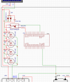
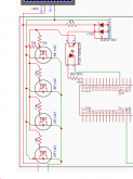
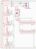
+5V, 40mA signal from microprocessor is reduced to 1.4V, 20mA that drives the IC817 optocoupler, acting as switch.
Isolated +12V is fetched from PV panels via Zener @1mA and fed to the optocoupler that would act as driver to feed Gate voltage of around +12V (Since its isolated now and is in reference to local PV ground) to 4 Power Mosfets IRF1407 - connected in parallel.
On saturation, all 4 Mosfets are expected to drain -45V side of PV panels and forwards it to -ive port of SCC - typically connecting the two and closing the circuit.

However a doubt remains - In case of a Mosfet does Vds and Vgs impact the voltage received at source end?
or to say Is Vds relative to Vgs?

Any and all comments are welcome, especially from critiques.
Complete schematic attached for ref.
Thanks
 

Attachments

  • Schematic.pdf
    136.2 KB · Views: 7
Last edited:
The capacitor should be in // with the zeners and pin 4 of the opto should be connected to the 50 k / zeners node (i.e. the other side of the capacitor as it's drawn right now).

Only one 10 k resistor is needed to force the gates to PV-.

I highly recommend to add a resistor in series with each gate (and as we don't really care about the turn-on time here you can use 10 k ones so you don't have to source multiples values), both to avoid degrading the opto with high current spikes, and to avoid a cascade failure if one of the IRF gates went to be shorted to the drain or source.

20 mA seems a bit high for an opto LED, I didn't check the datasheet but you need to make sure it's not right at the max of the opto specs (especially as the 1.4 Vf can vary a bit and the resistors have tolerances, you want to avoid going past the max), 12-15 mA is usually what I've seen for opto LEDs ;)

50 k isn't a norrmalized value, 47 k is. We usually pick in the E12 series: https://en.wikipedia.org/wiki/E_series_of_preferred_numbers#Lists and E24 when we really need more precision.
 
Last edited:
Doesn’t seem to me you have a 12V supply that’s above the 45V of the solar panels, unless there’s a dedicated gate supply (isolated solar panel).

I used P channel fets and don’t have this problem.
 
The 12 V used for the IFRs is supplied by the zeners powered from the PV ;)
 
Last edited:
Doesn’t seem to me you have a 12V supply that’s above the 45V of the solar panels, unless there’s a dedicated gate supply (isolated solar panel).

I used P channel fets and don’t have this problem.
As said we have Solar Panels delivering isolated drive supply through optocoupler.
P-Channel FETs have a much higher RDS(on) for 30Amp load in comparison with N-Channel.
But yes the implementation would have been easier.
 
Don’t see how that can work. That 12V is a portion of the 45V PV supply. Don’t think an isolator helps.
 
Channel resistance is higher, so what. Add a couple more fets.
 
Don’t see how that can work. That 12V is a portion of the 45V PV supply. Don’t think an isolator helps.
Shouldn't that be like how an SSR works? Hmm...thinking...
Well the second source we have is batteries but then it again would be shorting its ground with SCC and eventually the PVs - so wouldn't be completely isolated either.

I'm still trying to clear this up - are Vds and Vgs relative or do they act in absolute terms?
If they are relative locally then what impact does it bear on drain current?
Haven't found any substantial material online that specifies this clearly.

Channel resistance is higher, so what. Add a couple more fets.
Sure, but higher IR translates to higher losses/heat which we are trying to keep lean.
Hope something works out and don't have to take this route.
 
Last edited:
Shouldn't that be like how an SSR works? Hmm...thinking...

Yep, it'll work ;)

I'm still trying to clear this up - are Vds and Vgs relative or do they act in absolute terms?

They are always relative to the FET source unless noted otherwise. But you can express them relative to whatever you want, they are just voltages.
 
They are always relative to the FET source unless noted otherwise. But you can express them relative to whatever you want, they are just voltages.

So in our case if Source Voltage is +45 and Gate Voltage is +12V -> that leave a bandwidth of ~33V for Drain channel to be active.
Even in the case both voltages are non-isolated(share common ground), with a PD of >10 volts across the bridge - shouldn't this work?
My understanding was that as long as difference is +10V, RDS(on) should be low enough for Id to achieve its max Value.
 
What is your reference voltage? (i.e. the 0 V)

You need to say clearly what is your reference if you don't use the GND (or PV negative in this case).
 
Didn’t look carefully, you’re using a low-side switch.
 
With Changes incorporated:

1597369007197.png
Anything else remains to be checked/ optimized? ??
 

Attachments

  • Schematic.pdf
    135.3 KB · Views: 2
Good ;)

There's one error tho: the 10 k pull-down resistor shouldn't be connected to the gate of the first FET but to the common gate signal (pin 3 of the opto).
 
Reference voltage is fet source, which is connected to SCC negative. Probably SCC is connected to battery ground. Hence, reference voltage is battery gnd. The solar panels are floating. They have no bat gnd reference. That means 12V, coming from solar can not supply gate current. The circuit won’t work.
 
The sources are connected to PV negative, not SCC negative ;)

NB: I didn't saw you changed the opto LED resistor before but 350 Ohm isn't a standard value, 330 is ;)
 
  • Like
Reactions: Cal
Back
Top