You are using an out of date browser. It may not display this or other websites correctly.
You should upgrade or use an alternative browser.
You should upgrade or use an alternative browser.
Aluminum busbar instead of copper?
- Thread starter Ceefiveceefive
- Start date
Warpspeed
Solar Wizard
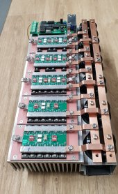
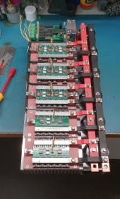
That is a functional piece of artwork Roger.
Far too pretty to power up.
Far too pretty to power up.
Last edited:
Ampster
Renewable Energy Hobbyist
I considered using Aluminum bus bars. One aspect was the cooling I would get from larger busbars. I also liked that fact that Aluminum was easier to drill. It turned out that getting large enough Aluminum was not as easy and I went for copper. I used NoAlox and applied it immediately after polishing the Aluminum terminal tops to reduce oxidation. The Aluminum to Copper interface is critical and some form of antioxidant on the aluminum terminal tops is critical to reduce resistance.
That is a functional piece of artwork Roger.
Far to pretty to power up.
Haha thanks, I was gonna go stainless steel ... but do you think a perspex cover would be legal?
I am a bit nervous to fire it up but need to finish off the transformers first.
Most of time engineering don't go with art this is not the case, you are a master, congrats.I prefer copper coz it's purdy. ?
Of course then I go spoil it all with heatshrink!!!
Now you have to anodise black the heatshrink or do a chemical blacking it will dissipate better.
Warpspeed
Solar Wizard
Just slowly bring your Warpverter to life bit by bit.I am a bit nervous to fire it up but need to finish off the transformers first.
Start by driving each inverter individually (without its transformer fitted) from the "large" driver waveform. The "large" waveform is a simple 50Hz square wave, so its a lot easier to interpret on the oscilloscope screen than the other more complex waveforms.
Don't be shy about adding dead time. The switching rate is so low, even several microseconds dead time is perfectly o/k.
When testing, it helps a lot to externally trigger your oscilloscope from the 50Hz "large" waveform when looking at other waveforms.
The other driver waveforms look a bit chaotic, and its difficult for the oscilloscope to find something to lock onto otherwise.
When starting out, expect to see massive overshoot on the secondaries of individual transformers.
And also expect to see some pretty crappy ragged looking voltage waveforms initially, that is all perfectly normal so do not panic !
As you start adding inverters, the waveforms smooth right out. With all four inverters working there will finally be a lovely perfectly smooth sine wave.
The reason for the crappy waveforms is that its very difficult for a transformer (any transformer) to generate a square wave current in the secondary.
Just as its very difficult to produce a perfect square wave voltage across a large capacitor.
So the transformers will not work very well into an open circuit or a resistive load individually.
It will ring, it will overshoot, and be very unhappy.
However, once you start combining the secondaries in series, a really interesting thing happens.
The voltage waveform begins to look more sinusoidal at 50Hz as the steps get smaller.
The current in the secondaries starts to become more sinusoidal as well.
With everything hooked up and working, the combined secondary current eventually becomes a perfect sinusoid, and that smooth unbroken sinusoidal secondary current is reflected back into every primary.
The transformers are very content working with a pure 50Hz sine wave current, and eddy current losses in the transformers will be low as well.
The voltages across all the individual transformer windings will be switching up and down like mad, and be perfectly rectangular and fast, without any sign of ringing or overshoot. But initially, when only part of the whole Warpverter is working, the waveforms can look pretty awful.
So be prepared for that !
Its all very robust. You can connect any inverter to any drive waveform, and any transformer to any inverter.
You can power up inverters without any drive plugged in, plug or unplug the drive waveforms under power.
And swap the phasing of individual inverters around without any mishap.
The final output may look a bit funny, if the phasing of one or more transformers is incorrect, but nothing is going to blow up.
Phasing can be swapped at the input drive to an inverter, or the transformer primary or the transformer secondary.
Whatever causes minimum aesthetic disturbance to the wiring.
Bringing a new Warpverter into the world has now been done by by many other people, and without any drama.
Its a fascinating exercise bringing one of these to life for the very first time.
Last edited:
yabert
Solar Enthusiast
It's a good point who can set the choose between both material. I can confirm that copper is way harder to CNC mill than Aluminum 6061-T6.I also liked that fact that Aluminum was easier to drill.
Copper stick a lot to the tool.
Below, milled copper busbar inside the junction box of a GM 2500HD electric truck and busbars for a modified Tesla drive.
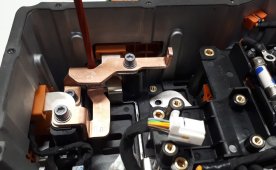
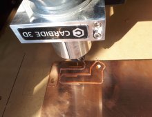
If we don't have the proper tools for copper we need to go slow and cutting fluid helps. I drill my bus bars yesterday with a standard HSS but good brand drill, didn't had problems but the one I have done without a bit of thread fluid became hot.
Most of time engineering don't go with art this is not the case, you are a master, congrats.
Wow, thanks for the kind words.
Now you have to anodise black the heatshrink or do a chemical blacking it will dissipate better.
Yeah I wasn't thinking when I planned this. I did have another heatsink that was already black so I should have chosen that. Has been a lot of drilling and tapping so I'd rather not have to do that again.
John Frum
Tell me your problems
- Joined
- Nov 30, 2019
- Messages
- 15,233
Are the conductors/heat sinks on top of the PCBs aluminum?I prefer copper coz it's purdy. ?
Of course then I go spoil it all with heatshrink!!!
Does the vertical back-plane sit on top of and/or connect to large capacitors?
Just slowly bring your Warpverter to life bit by bit.
Start by driving each inverter individually (without its transformer fitted) from the "large" driver waveform. The "large" waveform is a simple 50Hz square wave, so its a lot easier to interpret on the oscilloscope screen than the other more complex waveforms.
Don't be shy about adding dead time. The switching rate is so low, even several microseconds dead time is perfectly o/k.
When testing, it helps a lot to externally trigger your oscilloscope from the 50Hz "large" waveform when looking at other waveforms.
The other driver waveforms look a bit chaotic, and its difficult for the oscilloscope to find something to lock onto otherwise.
When starting out, expect to see massive overshoot on the secondaries of individual transformers.
And also expect to see some pretty crappy ragged looking voltage waveforms initially, that is all perfectly normal so do not panic !
As you start adding inverters, the waveforms smooth right out. With all four inverters working there will finally be a lovely perfectly smooth sine wave.
The reason for the crappy waveforms is that its very difficult for a transformer (any transformer) to generate a square wave current in the secondary.
Just as its very difficult to produce a perfect square wave voltage across a large capacitor.
So the transformers will not work very well into an open circuit or a resistive load individually.
It will ring, it will overshoot, and be very unhappy.
However, once you start combining the secondaries in series, a really interesting thing happens.
The voltage waveform begins to look more sinusoidal at 50Hz as the steps get smaller.
The current in the secondaries starts to become more sinusoidal as well.
With everything hooked up and working, the combined secondary current eventually becomes a perfect sinusoid, and that smooth unbroken sinusoidal secondary current is reflected back into every primary.
The transformers are very content working with a pure 50Hz sine wave current, and eddy current losses in the transformers will be low as well.
The voltages across all the individual transformer windings will be switching up and down like mad, and be perfectly rectangular and fast, without any sign of ringing or overshoot. But initially, when only part of the whole Warpverter is working, the waveforms can look pretty awful.
So be prepared for that !
Its all very robust. You can connect any inverter to any drive waveform, and any transformer to any inverter.
You can power up inverters without any drive plugged in, plug or unplug the drive waveforms under power.
And swap the phasing of individual inverters around without any mishap.
The final output may look a bit funny, if the phasing of one or more transformers is incorrect, but nothing is going to blow up.
Phasing can be swapped at the input drive to an inverter, or the transformer primary or the transformer secondary.
Whatever causes minimum aesthetic disturbance to the wiring.
Bringing a new Warpverter into the world has now been done by by many other people, and without any drama.
Its a fascinating exercise bringing one of these to life for the very first time.
Thanks for the detailed instructions Tony. I'm definitely getting closer so I'll keep them handy for when I finally fire it up.
I was able to see what the combined drives looked like via your simulator board, so I know that the drive is correct.
And I did try the boards without their transformers to make sure they actually work as designed. That was a big relief to see them running ok.
Would it pay to disconnect the capacitors before I drive the individual inverters into their transformer or is that not necessary?
Are the conductors/heat sinks on top of the PCBs aluminum?
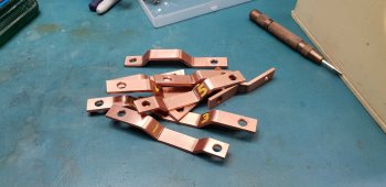
No, they are the same copper material as the horizontal links ... 12.7mm x 3mm
I tinned them first and then soldered them to the boards. I first tried to tin them by lowering them into a solder bath, but because the bath was not big enough the coating was not all that even.
Then I remembered that I had bought a 120w soldering iron many years ago ... so dragged it out and tried that. It worked extremely well. Only needed about 5 seconds to get hot enough to start the solder flowing!
The boards have 2 oz copper cladding and where the upper and lower bars are soldered on there is lots of stitching, so it worked pretty well I thought.
If I was to do it again, I would possibly try to tin only the side that was to attach to the board ... but it would be pretty hard to heat it well enough to 'float' onto the board without getting solder all over the top of the bars.
Does the vertical back-plane sit on top of and/or connect to large capacitors?
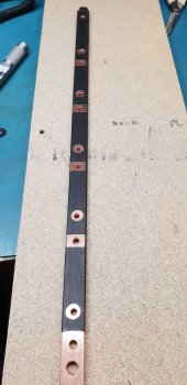
I'm not sure I'm with you ... do you mean the vertical busbars? They are connected to 6 large electrolytics.
Below, milled copper busbar inside the junction box of a GM 2500HD electric truck and busbars for a modified Tesla drive
Very nice. That is definitely art. Not sure what it is about copper but I love it when it's all new and polished up. Not so much once it's tarnished and green. ?
John Frum
Tell me your problems
- Joined
- Nov 30, 2019
- Messages
- 15,233
We are on the same page.I'm not sure I'm with you ... do you mean the vertical busbars? They are connected to 6 large electrolytics.
Warpspeed
Solar Wizard
What I do is use a soft start resistor to charge up the main capacitor bank. If something is terribly wrong, the voltage will simply refuse to rise.Thanks for the detailed instructions Tony. I'm definitely getting closer so I'll keep them handy for when I finally fire it up.
I was able to see what the combined drives looked like via your simulator board, so I know that the drive is correct.
And I did try the boards without their transformers to make sure they actually work as designed. That was a big relief to see them running ok.
Would it pay to disconnect the capacitors before I drive the individual inverters into their transformer or is that not necessary?
Its then possible to start disconnecting things to isolate the problem, without doing any serious damage.
As all your sub assemblies are already known to work, the whole thing should proceed without any drama.
It will need to have a soft start resistor anyway. I use a thirty ohm 300 watt resistor with my 100v battery.
It does not really need to be 300 watts, the inverter comes up to full output voltage in about two to three seconds.
The soft start resistor sees a terrific thermal shock, and a much lower powered resistor will work fine for a short time, then fail open circuit.
Something like 47 ohms 20 watts might get you plenty of starts with your 48v inverter, before it fails open circuit. But it will eventually fail.
My main purpose was to warn you to expect some pretty crappy looking output waveforms, during first initial testing.
I did not want you to feel with a sinking heart that the whole thing was a failure.
Keep going with the testing, and be prepared to be truly delighted with the eventual final result.
Last edited:
I read all your posts, but nobody seems to mention that mixing Cu and Al isn't exactly so simple. I'm building a replacement battery for Nissan Leaf and the batteries have aluminium contacts. So my thought was to install aluminium bus bars not just because of price savings but also I get rid of those nasty chemical reactions between copper and aluminium. Nickel plated copper bus bars introduce some additional resistance, which is not negligible when connecting 96 cells in series. So I'll use 1" x 1/6" (25mm x 4mm) bars, which should be more then enough. Max current will be 300A for couple of seconds, most of the time under 100A. Any thought is very welcome.
Warpspeed
Solar Wizard
Aluminium is tricky stuff, and readily develops an oxide film which is actually an insulator.
Even bolting aluminium to aluminium is not straightforward.
However, in the electrical trade, this is done all the time, and crimping aluminium conductors inside copper crimp lugs is a standard industry accepted process.
What makes this possible is an electrically conductive paste or grease which I think has small grains of zinc or silver that bites through the oxide layer, and keeps out the air.
Not sure of all the actual details, but this magic goo is sold under various product names around the world, and the one I know here in Australia is called "Alminox".
Should not be too difficult to track down something similar in your part of the world.
https://www.blackwoods.com.au/elect...nd-joint-elec-alminox-grey-alm325g/p/00670412
Last edited:
yabert
Solar Enthusiast
What!!! I want to see thatI'm building a replacement battery for Nissan Leaf
As it's possible to find crash Leaf with good battery at low cost, you should have a good reason to build a battery. Greater capacity or simple challenge?
Well, 25 x 4mm. That give 100mm2 x 0.6 (alu VS copper factor), so 60mm2 or close to 2/0 AWG.So I'll use 1" x 1/6" (25mm x 4mm) bars, which should be more then enough
It's way enough. I would probably go with 20x4 or 25x3 if this is available material.
Your aluminum cell terminals probably have a finish on them. If no, oxidation will caused bad conductivity.
When I build battery with aluminum busbars, I remove oxidation with a scotch brite and immediately apply a thin layer of No-Ox or Penetrox.
That ensure good conductivity at the contact by keeping moisture and oxidation out.
Last edited:
Warpspeed
Solar Wizard
That sounds like similar stuff to Alminox.I remove oxidation with a scotch brite and immediately apply a thin layer of No-Ox or Penetrox.
That ensure good conductivity at the contact by keeping moisture and oxidation out.
Its the proper approved way, and it definitely works.
Hedges
I See Electromagnetic Fields!
- Joined
- Mar 28, 2020
- Messages
- 20,687
The bolted aluminum I'm aware of is tin plated.
Square-D breaker boxes have several pieces bolted together for neutral, also for breaker lugs.
PG&E crimps lugs onto aluminum wires. I think the lugs are plated, but the wire isn't. Pressure breaks through native oxide.
Resistors - some are surge rated and can take a hit. I saw non surge rated resistors fail, replaced them with surge rated (small stuff on a PCB.)
Similar threads
- Replies
- 82
- Views
- 8K
- Replies
- 9
- Views
- 1K


