diy solar

diy solar

Custom Bus Bars From Copper Flat Bar

I spent the day at the storage lot yesterday and made good progress. The new step drill bits did a nice job. A quick swipe with sandpaper cleaned up the contact area nicely.

I hauled my drill press and chop saw to the storage lot and that worked out really well, but that drill press is really heavy even though it's a benchtop model.

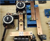
In the picture below, anything that is bright copper is new, the common bus bars (big shiny things) are also new. None of the devices are secured down, covers aren't on and the cable strain relief isn't in place yet either. All this in in preparation of wiring up my new inverter which calls for two cables on each DC leg (pos/neg), four total. I think this new setup is going to be more efficient. I have been stacking cable lugs on posts and I have to wonder if my batteries weren't as well balanced as they could be for charge and discharge. I'm referring mainly to the lugs on the shunt and the Class T fuse.

Some adjustments still need to be made. It's a little rough. I was out of time. It was dark, my flashlight batteries needed a charge and it was 35° F.

I am not impressed with the dinky little M6 studs on the Victron Battery Protect 65.

@noenegdod, the lowest speed on my drill press is 850 rpm. That's higher than I thought.

1643045760505.png
 
I drill copper by hand with an electric drill starting with a mechanical center punch.
View attachment 79307

Next is a 5/32"drill bit for pilot holes. All my drill bits are good quality 118° split point. I'll use any cutting oil that's around.

Step drilling 1/6" at a time keeps bits from getting plugged and breaking.

If the bar has hard wood/plastic (ViseGrip) clamped to it I'll drill thorough if not I stop 1/2 way and come in from the other side but that doesn't work as wall as the backing.

A counter sink removes the burr and make the bars look pro.

Most important is keeping the drill perpendicular to the surface.

That Diablo blade looks like it has a positive (a line along the face of the tooth crosses in front of the center hole) rake. A true non ferrous blade has a zero or a negative rake like this one has. Also note the backing for the teeth is shorter and much stronger.

View attachment 79309

***Be very very very careful cutting copper with a saw blade. I've seen people screw up and rip 10-15 teeth off a blade along with the backing for the teeth. I've also seen the motor come off the rails on compound saws. Cut through the smallest dimension. Make sure it is double/tripple clamped.

I like to used the lesser of 2 evils which is a Walter 1/16" zip cut wheel on a grinder but the copper gets scorching hot. I've seen people that don't know how to use a zip wheel destroy it by side loading or twisting it and have piecs of the disc embed in a wall 20' away.

This is the proper position to for a grinder when zip cutting. Most important is to always have it pulling away from you an


View attachment 79299
Wow. That’s nice. (Last pic)
 
Last edited:
I spent the day at the storage lot yesterday and made good progress. The new step drill bits did a nice job. A quick swipe with sandpaper cleaned up the contact area nicely.

I hauled my drill press and chop saw to the storage lot and that worked out really well, but that drill press is really heavy even though it's a benchtop model.

In the picture below, anything that is bright copper is new, the common bus bars (big shiny things) are also new. None of the devices are secured down, covers aren't on and the cable strain relief isn't in place yet either. All this in in preparation of wiring up my new inverter which calls for two cables on each DC leg (pos/neg), four total. I think this new setup is going to be more efficient. I have been stacking cable lugs on posts and I have to wonder if my batteries weren't as well balanced as they could be for charge and discharge. I'm referring mainly to the lugs on the shunt and the Class T fuse.

Some adjustments still need to be made. It's a little rough. I was out of time. It was dark, my flashlight batteries needed a charge and it was 35° F.

I am not impressed with the dinky little M6 studs on the Victron Battery Protect 65.

@noenegdod, the lowest speed on my drill press is 850 rpm. That's higher than I thought.


View attachment 81069
That looks good!

I found that the step drills seem to do a good job of cleaning up burs like a counter sink does.

850 RPM is still a pretty good clip. Im impressed you are able to do such a good job. Slowest speed on mine is 280 (max 3000) and I drill everything copper at that speed now. Just have to be super careful with small dia bits as they tend to grab and break.

Does your drill press have an idler pulley or just a primary and secondary? Mine has an idler and 2 belts which might be why it is so much slower.

It was dark and perhaps I didn't have the right reading/safety glasses on. 820 turned out to be 620 once I got a look at it in daylight.
nerd.gif


No idler pully. Just the primary pulley on the motor and the secondary on the spindle. It's a 25 year old Delta benchtop model that I've had since it was new. I checked to make sure the table was square to the bit in two directions and it was right on the money.
 
620 makes me feel a little better :). I was wondering what the hell I was doing wrong if you could pull it off at 820 and I certainly was not doing that well at 800.
 
Sanding around each of your bolt holes is probably a good idea for connectivity. I don't know about that flat bar but I know copper pipe has a "clear coat" on it to prevent it from turning green. I built a copper fountain for my KOI pond thinking it would turn a nice green patina but the coating stopped that until sanded off. One of my only youtube videos LOL.
 
Sanding around each of your bolt holes is probably a good idea for connectivity. I don't know about that flat bar but I know copper pipe has a "clear coat" on it to prevent it from turning green. I built a copper fountain for my KOI pond thinking it would turn a nice green patina but the coating stopped that until sanded off. One of my only youtube videos LOL.

If there is a clear coat on the flat bar, it's certainly gone after I dress the contact surface with sandpaper. I had considered treating the bus bars once there were in place with a quick spray of polyurethane to deter oxidation. But I'm going to let it go for now and see how it ages.
 
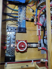
I’m curious about the arc interruption capacity of the air gap between bus bars. Some of those look pretty close.

If/when a moth lands and bridges the gap, I wonder if there could be a problem? That is, how much space between bus bars would be needed at a given voltage?A1AC2F28-AEF9-4DBE-BB7F-AB8AEB58CF8E.jpeg
 
I’m curious about the arc interruption capacity of the air gap between bus bars. Some of those look pretty close.

If/when a moth lands and bridges the gap, I wonder if there could be a problem? That is, how much space between bus bars would be needed at a given voltage?View attachment 82327

I had the same concern and asked that question here: https://diysolarforum.com/threads/how-close-can-bare-copper-bus-bars-be-12v.30555/

Not so much about a moth but if the battery protects were to open while the winches that are down stream from the battery protects were operating, would 12v jump that gap. Just to be clear, the two bars that are really close are both positive. That thread exposed a few other issues I had and was able to work out a solution that should address all the issues.

I am also thinking about greasing up the bars and the battery protect and extruding some silicone between them to absolutely prevent any chance of any kind of unwanted current between the two bars.
if arcing is a concern, you could consider using shrinkwrap, or plastic bar cover
 
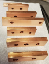
The latest set of bus bars. I did a better job this time with cleaning off the Tap Magic drill lube. After cutting the bars to length and drilling the holes I cleaned them with brake parts cleaner, then a light sanding of the contact surfaces, paper towel to remove most of the dust and then denatured alcohol on a paper towel to get them good and clean.

The dinky little bar hiding in the back is for a low amp connection. The rest of them are for connections to the inverter or coming from the battery. The holes are in different spots depending upon what the bus bar will be installed on.

1644789686339.png
 
3/8" thick by 1" wide. I got a decent deal on the 3/8", so I thought I would put it in.

The one in back is 1/8" by 3/4". I needed to use the thinner stuff there because I need to bend it to fit. No way I can bend the 3/8" bar.
 
Is there any concern about the interface between the lugs and bare copper busbar increasing resistance over time or will that be prevented by having the lug on there to begin with?
 
Back
Top