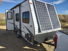
I'm have no prior experience or education in this field, been living in a travel trailer for 2 years now and I final got everything installed and working. That being said I'm not only nervous but confused by my solar charger, not being an expert I don't understand why it's current doesn't add up too the watts the volts timed by the amps equals. Along with the hindsight that I could, maybe should, have wired the solar charger directly to the RVs fusebox. At the moment the solar charger is connect to bus bars that go to both RVs DC and the batteries instead of independently judging from the solar charger. If anyone can tell what I've done both right and wrong I'd greatly appreciate any advice!


You are using an out of date browser. It may not display this or other websites correctly.
You should upgrade or use an alternative browser.
You should upgrade or use an alternative browser.
Amauter hour
- Thread starter Zelabull
- Start date
MisterSandals
Participation Medalist
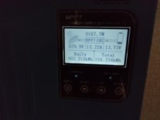
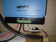
Your display shows it is charging:I don't understand why it's current doesn't add up too the watts the volts timed by the amps equals.
12.22A x 13.73V = 167W
No the SCC charges the battery. The battery provides power to the fusebox. Don't make it more complicated.Along with the hindsight that I could, maybe should, have wired the solar charger directly to the RVs fusebox.
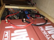
Speaking of which, your battery wiring looks unusual. Do you have 2 batteries wired in parallel or ?? Can you post a pic that shows the wiring a little better?
In both of the pictures you show, the battery voltage times the amps does equal the watts. For example, in the last picture it shows the battery voltage as 13.73V and the charging amps as 12.22A. That equals 167.78W. The display shows 167.7W.I don't understand why it's current doesn't add up too the watts the volts timed by the amps equals.
I assumed the 13.73V was the batteries voltage when equaling the solar panels Voltage it doesn't add up. I know the charge lowers when the batteries are getting full but for my solar panels it seems too low for what the panels are rated for.Your display shows it is charging:
12.22A x 13.73V = 167W
No the SCC charges the battery. The battery provides power to the fusebox. Don't make it more complicated.
Speaking of which, your battery wiring looks unusual. Do you have 2 batteries wired in parallel or ?? Can you post a pic that shows the wiring a little better?
Will do
Last edited:
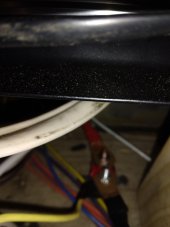
On the solar charger it has the light bulb output that is for DC which the 4th pic is from my understanding. Currently I have it connected to the bus bar, but wouldn't it not read a full charge if not connected solely to the battery if its consistently being used for RVs DC?Your display shows it is charging:
12.22A x 13.73V = 167W
No the SCC charges the battery. The battery provides power to the fusebox. Don't make it more complicated.
Speaking of which, your battery wiring looks unusual. Do you have 2 batteries wired in parallel or ?? Can you post a pic that shows the wiring a little better?
Attachments
Last edited:
To clarify isn't the Voltage rating on the right the readings for the batteries but the left is the solar panels. I'm just making sure that when finding the charge rate don't I use the panels voltage?In both of the pictures you show, the battery voltage times the amps does equal the watts. For example, in the last picture it shows the battery voltage as 13.73V and the charging amps as 12.22A. That equals 167.78W. The display shows 167.7W.
The job of the charge controller is to take the incoming wattage (whatever that voltage and amperage is) and convert it to the battery charge voltage and current. The panel voltage does not give you the charge rate.To clarify isn't the Voltage rating on the right the readings for the batteries but the left is the solar panels. I'm just making sure that when finding the charge rate don't I use the panels voltage?
If there are 167W coming in from the panels at the moment then the controller will convert that 167W into a charge voltage and current. That charge voltage and current will still be 167W.
The above assumes an MPPT charge controller.
Okay that makes sense so the voltage on the left is intake and the voltage on the right is outgoing, I was using the wrong voltage in my calculations thanks!The job of the charge controller is to take the incoming wattage (whatever that voltage and amperage is) and convert it to the battery charge voltage and current. The panel voltage does not give you the charge rate.
If there are 167W coming in from the panels at the moment then the controller will convert that 167W into a charge voltage and current. That charge voltage and current will still be 167W.
The above assumes an MPPT charge controller.
MisterSandals
Participation Medalist
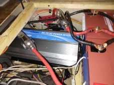
I am confused by your battery wiring. You have the 2 wired together in parallel properly and a positive from one battery and negative from the other as expected. But why 2 wires from each battery going to the abyss in back? Its sort of a double paralleling if they are to a bus bar, not so good if going to individual loads. Confusing to me.
Power inverter not much space so no picture for wiring sorryI am confused by your battery wiring. You have the 2 wired together in parallel properly and a positive from one battery and negative from the other as expected. But why 2 wires from each battery going to the abyss in back? Its sort of a double paralleling if they are to a bus bar, not so good if going to individual loads. Confusing to me.
MisterSandals
Participation Medalist
I do not know how that works, i have never seen that.Power inverter not much space so no picture for wiring sorry
With 2 batteries in parallel, you are supposed to pull loads from the 2 ends of the battery bank: in your picture, that would be all positive from far left post on battery 1, and all negative from far right post on battery 2.
This might keep me up at night...
@smoothJoey - glad you're here. What are your thoughts on this?
Yeah that's what's going on the inner wires go to the bus bar, with a 100A fuse, and the outer wires go to the inverter, 300A fuse both are getting a positive and a negative from the batteries.I do not know how that works, i have never seen that.
With 2 batteries in parallel, you are supposed to pull loads from the 2 ends of the battery bank: in your picture, that would be all positive from far left post on battery 1, and all negative from far right post on battery 2.
This might keep me up at night...
@smoothJoey - glad you're here. What are your thoughts on this?
Just relooked at picture, in your defense I understand the confusion bad pictureI do not know how that works, i have never seen that.
With 2 batteries in parallel, you are supposed to pull loads from the 2 ends of the battery bank: in your picture, that would be all positive from far left post on battery 1, and all negative from far right post on battery 2.
This might keep me up at night...
@smoothJoey - glad you're here. What are your thoughts on this?
Bud Martin
Solar Wizard
- Joined
- Aug 27, 2020
- Messages
- 4,843
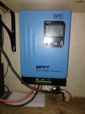
On the first picture I see PV Red and Black wires of PV panels connected to the PV input terminals, then I see small Red wire with 100A circuit breker connected to the + of the SCC Battery terminal, then the small White wire connected to the - of the SCC Negative terminal to goes to some where, is that correct?On the solar charger it has the light bulb output that is for DC which the 4th pic is from my understanding. Currently I have it connected to the bus bar, but wouldn't it not read a full charge if not connected solely to the battery if its consistently being used for RVs DC?
May be you should draw out the wiring diagram so we can see how the system is wired up.
Yes, it is confusing to see each battery has Red wire on each battery with in-line fuse that branch out from the battery bank, based on the picture #3 the positive of the left battery is connected to the inverter through the fuse, the positive of the right battery is connected to the busbar through the fuse, correct? So the Red wire from the SCC that is connected through 100A breaker is connected to that same busbar? I have no idea where the White from SCC goes to. I also do not see anything connected to the switched 'LOAD/LAMP' output terminals.
The SCC negative, white wire, goes to the negative bus bar. That was a second question the RVs DC is connected to the system by the bus bars, should I install them to the SCC directly or leave it like it is. Hope this helps...On the first picture I see PV Red and Black wires of PV panels connected to the PV input terminals, then I see small Red wire with 100A circuit breker connected to the + of the SCC Battery terminal, then the small White wire connected to the - of the SCC Negative terminal to goes to some where, is that correct?
May be you should draw out the wiring diagram so we can see how the system is wired up.
Yes, it is confusing to see each battery has Red wire on each battery with in-line fuse that branch out from the battery bank, based on the picture #3 the positive of the left battery is connected to the inverter through the fuse, the positive of the right battery is connected to the busbar through the fuse, correct? So the Red wire from the SCC that is connected through 100A breaker is connected to that same busbar? I have no idea where the White from SCC goes to. I also do not see anything connected to the switched 'LOAD/LAMP' output terminals.
Attachments
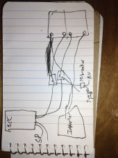
Since I have no idea what your trying to say is confusing can you do the same, draw a quick wiring diagram of what you'd expect it to look like if done your way....On the first picture I see PV Red and Black wires of PV panels connected to the PV input terminals, then I see small Red wire with 100A circuit breker connected to the + of the SCC Battery terminal, then the small White wire connected to the - of the SCC Negative terminal to goes to some where, is that correct?
May be you should draw out the wiring diagram so we can see how the system is wired up.
Yes, it is confusing to see each battery has Red wire on each battery with in-line fuse that branch out from the battery bank, based on the picture #3 the positive of the left battery is connected to the inverter through the fuse, the positive of the right battery is connected to the busbar through the fuse, correct? So the Red wire from the SCC that is connected through 100A breaker is connected to that same busbar? I have no idea where the White from SCC goes to. I also do not see anything connected to the switched 'LOAD/LAMP' output terminals.
MisterSandals
Participation Medalist
As pictured this would not work. You have the batteries connected to each other too.The SCC negative, white wire, goes to the negative bus bar. That was a second question the RVs DC is connected to the system by the bus bars, should I install them to the SCC directly or leave it like it is. Hope this helps...
I really do not know what to think with your loads wired to different pairs of posts.
I would not connect and loads to the SCC load terminals if that is what you are asking. Those are generally for very light, often timed loads (like night lights). My thought is that making the SCC do this work when the battery gladly does it puts unnecessary stress on the SCC.
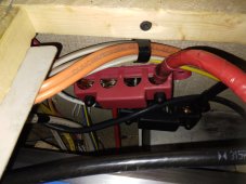
I like how you have a dedicated set of wired to your inverter because it allows you to easily choose the correct fuse or breaker. Probably much bigger than would be useful to your RV loads.
I think if you put all the connections to the batteries on one set of terminals (positive on one battery, negative on the other) it would be as balanced as it can get. Whether it will work as you have it i cannot tell.
That's what's going on didn't draw the wires that connects the batteries in parallel, cause all pictures showed it. As for the balance of positive from one battery and the negative from the other that is what's happening, but the negative wires in all pictures look connected or the same, they are not for record and split like you said from RV DC and SCC, bus bars, but the inverter separately has its own wires, and connected to the circuit breaker for RVs 12v directly to inverter. Thanks I wasn't sure if the SCC lamp load was necessary for reducing stress from the batteries, glad you think DC isn't an issue in that regards.As pictured this would not work. You have the batteries connected to each other too.
I really do not know what to think with your loads wired to different pairs of posts.
I would not connect and loads to the SCC load terminals if that is what you are asking. Those are generally for very light, often timed loads (like night lights). My thought is that making the SCC do this work when the battery gladly does it puts unnecessary stress on the SCC.
I like how you have a dedicated set of wired to your inverter because it allows you to easily choose the correct fuse or breaker. Probably much bigger than would be useful to your RV loads.
I think if you put all the connections to the batteries on one set of terminals (positive on one battery, negative on the other) it would be as balanced as it can get. Whether it will work as you have it i cannot tell.
MisterSandals
Participation Medalist
Its an easy change to use one set of terminals for your loads and get it right, for sure. I'm still scratching my head on using 2 different pairs of terminals, my gut feel is that is will cause some imbalance but my head says it won't.glad you think DC isn't an issue in that regards.
Oh now I see what your saying I heard the opposite, before installing, so the charge flow comes in through one set of terminals they said it would distribute the stress if giving the draining current its own set.Its an easy change to use one set of terminals for your loads and get it right, for sure. I'm still scratching my head on using 2 different pairs of terminals, my gut feel is that is will cause some imbalance but my head says it won't.
Similar threads
- Replies
- 88
- Views
- 3K
- Replies
- 16
- Views
- 496
- Replies
- 15
- Views
- 560
- Replies
- 28
- Views
- 1K