diy solar

diy solar

Another wire size question: 4 inverters in parallel

EscapedAritst

New Member
Joined
Oct 2, 2021
Messages
31
Location
Costa Rica
I finally pulled the trigger. I just purchased a system...my first! This is the spec:

- 4 EG4 48v 6500 inverters for split phase off-grid application
- 6 EG4 batteries (to be doubled after systems up and running and tested)
- 36 panels of 450 watt panels (not important but comments welcomed)

And now I'm planning the wiring. When I read the PDF from FilterGuy called "Calculating Inverter Wire Size.pdf", I calculate the following:
( 6500w / .9 (efficiency) / 48v ) * 1.25 = 188 amps per inverter. I can position the batteries near the inverters so I am planning on the longest cable being 2m.

On Will's wiring diagram for a similar system, I see he has protected each inverter with a 200amp T class fuse. This is inline with my calculation above. BUT, when I use FilterGuy's wire size chart, I see the wire size for a 200amp fuse at 90deg C is 2AWG, Will is using 2/0 wire, and when I look up on a wire size calculator (www.southwire.com), I get 3/0 required. So, the first question is what is the discrepancy and how do I make an informed decision? FilterGuy puts an example in his PDF with an inverter he calculates a 180amp draw (24V 3000W inverter with 90%) and he uses 1AWG cable for safety but says a 2AWG would work.

Even more alarming is that Will connects two parallel inverters (I am assuming that will double the amperage? No??) but has a 300amp busbar feeding these two inverters and only a 4/0 cable feeding from one of his battery banks. My wire size calculator requires multiple cables when the amps go up to 360.

And finally, because I'm going to be connecting 4 of these inverters but having just one battery bank feeding them, it seems like no sized single cable could handle 752amps (that is 4 inverters times 188amps each). I don't even think the busbar of my battery case will support this.

Knowing that you can stack 6 of these inverters, I know I must be missing something really basic.

Thanks!
 
Just remember that the breakers are sized to protect the cable from overcurrent meltdown (from the inverters to the bus bar or batteries). The battery modules have their own breakers. Suppose one didn't put inverter breakers, then an overcurrent situation would increase up to the sum of all, of each breaker added together in all the battery modules to trip one (which could be hundreds of amps at the bus bar, then spread to lower amperage across all packs), and then the rest of the breakers might trip very soon after in a cascading fashion.

So for this reason, each inverter cable run back to the many-to-one battery connection point or bus bar needs their own breaker. So make sure you use a cable size that goes with your breaker size (factoring the 80% rule, which is breaker size is 80% of the cable ampacity)... Size of cable and amperage also have a lot to do with temperature the cable will run, and voltage drop. If you look at an ampacity chart, you can also factor in how hot you want to allow the cable to operate. As the cable gets hotter voltage drop goes higher yet. Also have to check the temperature rating of the cable insulation to make sure it can handle operating at the temperature it could see in a max current flow state.

Just some things to think about in selecting the cable. It doesn't hurt to go bigger, than too small...

Compare the various temperature points across cable sizes and same amperage point:
 
Last edited:
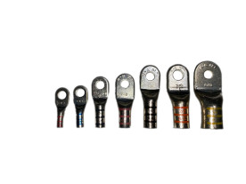
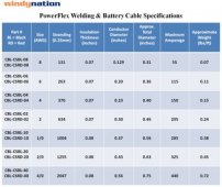
Based on your amperage requirements and large cable sizing, I would recommend going with Class K or M welding cable. Its sooo much more flexible and easier to work with. Keep in mind that the fine strands expand more when stripped so special crimp lugs with a slightly larger barrel are required. They are referred to as welding cable lugs or sometimes DLO cable lugs.
 
Just remember that the breakers are sized to protect the cable from overcurrent meltdown (from the inverters to the bus bar or batteries). The battery modules have their own breakers. Suppose one didn't put inverter breakers, then an overcurrent situation would increase up to the sum of all, of each breaker added together in all the battery modules to trip one (which could be hundreds of amps at the bus bar, then spread to lower amperage across all packs), and then the rest of the breakers might trip very soon after in a cascading fashion.

So for this reason, each inverter cable run back to the many-to-one battery connection point or bus bar needs their own breaker. So make sure you use a cable size that goes with your breaker size (factoring the 80% rule, which is breaker size is 80% of the cable ampacity)... Size of cable and amperage also have a lot to do with temperature the cable will run, and voltage drop. If you look at an ampacity chart, you can also factor in how hot you want to allow the cable to operate. As the cable gets hotter voltage drop goes higher yet. Also have to check the temperature rating of the cable insulation to make sure it can handle operating at the temperature it could see in a max current flow state.

Just some things to think about in selecting the cable. It doesn't hurt to go bigger, than too small...

Compare the various temperature points across cable sizes and same amperage point:
Hi Samsonite, thanks for your comments. I think I have the solution. I will have 6 batteries and they define my limit. I must support 600amp (each battery being 100amp max). If I run less than 1m off of the server rack bus bar, I can use 500 MCM and connect to a greater than 600amp bus bar, I can then connect each of the inverters with a 2/0 wire from the bus bar to their fuse and to the inverter and I should be all set. I still have a big problem if I grow the system to say 3 server racks (the ultimate plan), but I guess that I could somehow keep them separate. I think that out another day.

The thing that was confusing me was Will's wire diagram, but he only has two inverters which cannot ever pull 600amps from the batteries. In my case, with 4 inverters, I can go well over any AWG wire size and I got confused.
 
Based on your amperage requirements and large cable sizing, I would recommend going with Class K or M welding cable. Its sooo much more flexible and easier to work with. Keep in mind that the fine strands expand more when stripped so special crimp lugs with a slightly larger barrel are required. They are referred to as welding cable lugs or sometimes DLO cable lugs.
Hey Bentley, thanks for the comment. Where do I shop those cables/lugs?

Thanks.
 
The thing that was confusing me was Will's wire diagram, but he only has two inverters which cannot ever pull 600amps from the batteries. In my case, with 4 inverters, I can go well over any AWG wire size and I got confused.

I wouldn't say 'cannot ever pull'. Under normal operation you might be right, but if a transistor or some internal circuit board components melt down and internally short, even 1 inverter could try to draw as much as the batteries have the ability to supply to feed the short.

BTW, I've seen a long wire melt all the insulation off and glow bright yellow, and it's a nerve-wracking sight to see for sure, when the only thought on the mind was, I think I have the Leatherman cutters in the glovebox (lucky it was there or my car would've burned to the ground).

The protection is always to protect a wire from an overcurrent, but also for the worst case, which is a 0 Ω dead short at full amperage that the wire can flow until the short melts itself open, maybe the wire itself eventually might melt and break the circuit, or the battery goes dead, whichever comes first!

Or even if someone accidentally shorted it with a tool or something, we hope that would never happen, but they do call it 'overcurrent protection device' for a reason.
 
Last edited:
I still have a big problem if I grow the system to say 3 server racks (the ultimate plan), but I guess that I could somehow keep them separate. I think that out another day.

The thing that was confusing me was Will's wire diagram, but he only has two inverters which cannot ever pull 600amps from the batteries. In my case, with 4 inverters, I can go well over any AWG wire size and I got confused.

6500 ac watts / .85 conversion factor / 48 volts low cutoff = 159.31372549 inverter amps
159.31372549 inverter amps * 4 inverters = 637.254901961 service amps

Each rack has its own busbar.
Consider each rack a logical unit and connect them to a lynx-power-in with 4/0 awg wire and a 400 amp class-t fuse.
Connect the backplane of the lynx-power-in to a lynx-distributor.
Connect each inverter to the lynx distributor via 1/0 awg with a 250 amp mega fuse.

Use equal length wires for the inverters and the racks so that path resistance is as equitable as possible.
 
Hey Bentley, thanks for the comment. Where do I shop those cables/lugs?
I've purchased from WireandCableYourWay.com for the welding cable. There are several other choices of sellers that will come up with an internet search.
The compression lugs are more difficult to find especially from the typical consumer oriented online stores. Burndy brand produced by Hubbell Products is generally available through the electrical supply houses that cater to contractors. ElecDirect.com, Platt, Graybar, Rexel, Anixter, CED (Consolidated Electrical Distributors) Grainger but they tend to be expensive.
It may be easier to search through the Hubbell website and find the part numbers you need then do an internet search with the part number and exact description.
 
6500 ac watts / .85 conversion factor / 48 volts low cutoff = 159.31372549 inverter amps
159.31372549 inverter amps * 4 inverters = 637.254901961 service amps

Each rack has its own busbar.
Consider each rack a logical unit and connect them to a lynx-power-in with 4/0 awg wire and a 400 amp class-t fuse.
Connect the backplane of the lynx-power-in to a lynx-distributor.
Connect each inverter to the lynx distributor via 1/0 awg with a 250 amp mega fuse.

Use equal length wires for the inverters and the racks so that path resistance is as equitable as possible.
Hi John,

This helps a lot...time to study some more! I've never even seen the Lynx stuff but the wire sizes you are showing here seem in line with a safe version of my calculations. However, I'm finding radical difference in some wire calculators. Is there a DC calculator that is considered unimpeachable?
 
Is there a DC calculator that is considered unimpeachable?

No. :)

ABYC and NEC free air are very close though.

I go with pure copper wire with 105C insulation.
I fuse for the wire.
6 awg gets 100a fuse
4 awg gets 150a fuse
2 awg gets 200a fuse
0 awg gets 250a fuse
00 awg gets 300a fuse
0000 awg gets 400a fuse

 
Last edited:
The User Manual specifies 1/0 or 2/0. I'm using 1/0 fine wire 105C cable on my two EG4 6500ex. It also says 250aH of battery per inverter. I'll have 500aH on my EG4's. That's 10 ea of your batteries minimum. I have 10 ea 280aH's on my two Sol-Ark 12K's. You'll need a bus bar pair like mine for the 12K's. 1/4" x 2.5" x 7', tin plated copper. Then you should never see more than 60A discharge per battery. My max is 37A per battery.
 
Hey Bentley, thanks for the comment. Where do I shop those cables/lugs?

Thanks.

Just to add some more links for your quest.


30FEDCCF-74FE-43EC-B5A9-723AFBD47AA9.jpeg
 
I've purchased from WireandCableYourWay.com for the welding cable. There are several other choices of sellers that will come up with an internet search.
The compression lugs are more difficult to find especially from the typical consumer oriented online stores. Burndy brand produced by Hubbell Products is generally available through the electrical supply houses that cater to contractors. ElecDirect.com, Platt, Graybar, Rexel, Anixter, CED (Consolidated Electrical Distributors) Grainger but they tend to be expensive.
It may be easier to search through the Hubbell website and find the part numbers you need then do an internet search with the part number and exact description.
Hi BentlyJ,

Thanks again for your comments! You were right about the compression lugs!! I'm really trying to get this install to spec and it is tough. The battery, the server rack, and the inverter do not mention their terminator sizes. I guess you just modify existing lugs to fit?
 
@EscapedAritst have you considered mechanical lugs?

I like these https://www.panduit.com/content/dam/panduit/en/products/media/4/64/664/8664/110108664.pdf
They are not cheap but they are convenient.
Suggest you use ferrules if you use fine stranded wire.
Hi John,

What a rabbit hole I'm down. The mechanical lugs look like they are all aluminum and I'm trying to avoid that. However, I didn't even know what ferrules were and spent a good hour down that hole just researching crimpers, sources, and sizes. That is a great technology even outside this solar system I'm building. I don't know how I'd never been introduced to those before. Thanks!!
 
Back
Top