diy solar

diy solar

Batteries wired in parallel

TheBreeze

The Breeze
Joined
May 27, 2021
Messages
80
I've read, in this forum, that bus bars with equal length cables is the preferred method for wiring batteries in series. The submitted argument was that electricity seeks the shortest path and wiring all batteries to a bus bar reduces path length, allowing all batteries to equally participate in draw-down and recharge cycles.

The argument is that the batteries are measured in duty cycles and a battery at an endpoint will endure more cycles than the ones connected to it. Furthermore, once the endpoints receive a reach their recharge point, they are further taxed by recharging the batteries 'in the middle', consuming additional cycles to achieve balance.

Some on other forums ( e.g. youtube) advocate wiring batteries in series by connecting the positive and negative terminals of the batteries to each other and separating the endpoints, with one battery at the head of the positive, another the head of the negative power distribution.

Why does this contradiction exist? Is it a matter of economics (cost vs. benefit) or is it just a shortcut? A lot of youtubers build 'pretty installations. My question is what is the correct approach to wiring batteries for consumption and recharge.

Thanks for your time.
 
I've read, in this forum, that bus bars with equal length cables is the preferred method for wiring batteries in series PARALLEL. The submitted argument was that electricity seeks the shortest path and wiring all batteries to a bus bar reduces path length, allowing all batteries to equally participate in draw-down and recharge cycles.

Fixed.

The argument is that the batteries are measured in duty cycles and a battery at an endpoint will endure more cycles than the ones connected to it. Furthermore, once the endpoints receive a reach their recharge point, they are further taxed by recharging the batteries 'in the middle', consuming additional cycles to achieve balance.

Accurate, but overwhelmingly overstated.

Some on other forums ( e.g. youtube) advocate wiring batteries in series PARALLEL by connecting the positive and negative terminals of the batteries to each other and separating the endpoints, with one battery at the head of the positive, another the head of the negative power distribution.

Fixed.

Why does this contradiction exist? Is it a matter of economics (cost vs. benefit) or is it just a shortcut? A lot of youtubers build 'pretty installations. My question is what is the correct approach to wiring batteries for consumption and recharge.

Thanks for your time.

See link #5 in my signature.
 
I've read, in this forum, that bus bars with equal length cables is the preferred method for wiring batteries in series.

Parallel, not series.
The submitted argument was that electricity seeks the shortest path and wiring all batteries to a bus bar reduces path length, allowing all batteries to equally participate in draw-down and recharge cycles.

It's the resistance of the circuit that determines how many electrons flow. Electricity doesn't seek shortest path, it merely flows more on the path of least resistance. One could have a cable that is twice is long but much larger diameter and as long as the cable resistance is the same, from end to end, of a smaller diameter cable that is shorter, the current will flow equally. The smaller cable resistance will change slightly due to heating (thus changing resistance) and for a constant load this could have an effect.

The idea behind equal length cables to a busbar is the circuit resistance from a battery to the busbar is exactly the same.

The argument is that the batteries are measured in duty cycles and a battery at an endpoint will endure more cycles than the ones connected to it. Furthermore, once the endpoints receive a reach their recharge point, they are further taxed by recharging the batteries 'in the middle', consuming additional cycles to achieve balance.

Just wow, that is a real stretch there.

Once you understand the resistance of the circuit is what causes imbalance between batteries, then you will realize someone is not very knowledgeable and is making things up.

Some on other forums ( e.g. youtube) advocate wiring batteries in series by connecting the positive and negative terminals of the batteries to each other and separating the endpoints, with one battery at the head of the positive, another the head of the negative power distribution.

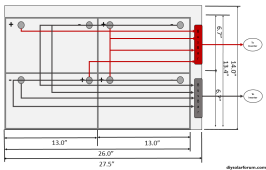
It helps with battery balance in parallel but it is not perfect balance. I run a 4 battery bank in my house. There is a large busbar that runs down each side of the box and each battery is connected to that busbar. On the positive busbar, the cable to the inverter is at the midpoint between 1&2, the negative is between 3&4. This is much preferred to keep batteries in balance. If there are only 2 batteries, the opposing cable connections method will suffice.

Why does this contradiction exist? Is it a matter of economics (cost vs. benefit) or is it just a shortcut? A lot of youtubers build 'pretty installations. My question is what is the correct approach to wiring batteries for consumption and recharge.

Thanks for your time.
 
This is where I keep running into trouble on this topic. Some state it's correct and others state it's something else entirely.
Maybe I belong in the newb thread because I don't fully understand the nuances and trying to learn. This will be a vehicle mounted system, so I thought it correct to pose the question here?
The argument is that the batteries are measured in duty cycles and a battery at an endpoint will endure more cycles than the ones connected to it. Furthermore, once the endpoints receive a reach their recharge point, they are further taxed by recharging the batteries 'in the middle', consuming additional cycles to achieve balance.

Accurate, but overwhelmingly overstated.
The argument is that the batteries are measured in duty cycles and a battery at an endpoint will endure more cycles than the ones connected to it. Furthermore, once the endpoints receive a reach their recharge point, they are further taxed by recharging the batteries 'in the middle', consuming additional cycles to achieve balance.

Just wow, that is a real stretch there.

Once you understand the resistance of the circuit is what causes imbalance between batteries, then you will realize someone is not very knowledgeable and is making things up.

Now I'm just confused. Who's correct here? If both are correct, please explain?
Thanks.
 
Last edited:
This is where I keep running into trouble on this topic. Some state it's correct and others state it's something else entirely.
Maybe I belong in the newb thread because I don't fully understand the nuances and trying to learn. This will be a vehicle mounted system, so I thought it correct to pose the question here?

Did you check link #5 in my signature? There's a section discussing parallel connection of batteries.
 
  • Like
Reactions: Zwy
Now I'm just confused. Who's correct here? If both are correct, please explain?
Thanks.
I'm not certain what you are asking as the post was mixed between your posts and mine.

The key to keep batteries in balance is circuit resistance. If the resistance is the same across the circuit, then batteries remain in balance. This is why battery cable lengths for both positive to a busbar need to be the same length and why both cable leads for the negative to a busbar need to be the same length. The negative and positive cables do not need to be the same length.

The story about duty cycle is hogwash.

I could add a link to a thread but it might confuse you more until you understand what I wrote above. Forget all those things about duty cycle or other information you received off some chat room.
 
Did you check link #5 in my signature? There's a section discussing parallel connection of batteries.
Yes and it all made complete sense. I saved it off for future reference.

I was headed in that direction until the resistance topic was mentioned when @Zwy chimed in. I understand resistance and had to question myself. I'm trying to get properly lined up so don't burn the RV to the ground or have to redo all this 6 months down the road.

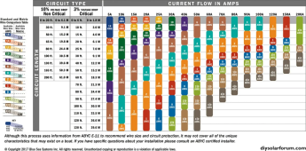
I have 4 BB 100AH LifePo4 batteries with built-in BMS. They're to be mounted in a RV with 4awg equal-length connections of 18" to the nearest 5-post bus bar. The remaining center lug is for 4/0 welding cable going to a 2.5kw AIMs inverter/charger/xfr switch. I chose the wire gauges based on the following chart. I chose 4/0 to the inverter for it's 10ft run and plan a 300A fuse close to the battery bank. I chose 10-3 stranded wire for marine applications because I'm working on an existing structure and the run was such I couldn't tie it down like solid wire but every so often. Solid wire has a tendency to break from bouncing and vibration.
1694550766850.png

The RV's power distribution panel has two sides: 120 and 12. I'll wire the RV's existing xfr switch to the inverter's AC input and send it back through the inverter's AC output connection to the 30A panel breaker. This should support receiving power from conventional sources while enabling power from the batteries for full-house 120v in all scenarios. The 12v circuits will come off the existing 12v lead back to the 12v side of the distribution panel.

There is a plan for 1320 watts solar on the roof in a 2S2P configuration. I'm still working on some details (e.g. MPPT controller(s).

If @Zwy is correct, why do so many sites measure battery life in duty cycles and DoD and he suggests I negate duty cycle?

Search keywords: battle born lifepo4 lithium battery duty cycle explained

Hit examples:
"Able to run 3,000 cycles, most people will have these batteries for 10 to 15 years".
https://battlebornbatteries.com/faq/ (see video)


I tried not to be verbose. Let me know if you need more info and thanks for the feedback.
 
Yes and it all made complete sense. I saved it off for future reference.

I was headed in that direction until the resistance topic was mentioned when @Zwy chimed in. I understand resistance and had to question myself. I'm trying to get properly lined up so don't burn the RV to the ground or have to redo all this 6 months down the road.

I have 4 BB 100AH LifePo4 batteries with built-in BMS. They're to be mounted in a RV with 4awg equal-length connections of 18" to the nearest 5-post bus bar. The remaining center lug is for 4/0 welding cable going to a 2.5kw AIMs inverter/charger/xfr switch. I chose the wire gauges based on the following chart. I chose 4/0 to the inverter for it's 10ft run and plan a 300A fuse close to the battery bank. I chose 10-3 stranded wire for marine applications because I'm working on an existing structure and the run was such I couldn't tie it down like solid wire but every so often. Solid wire has a tendency to break from bouncing and vibration.

This will work just fine.

If @Zwy is correct, why do so many sites measure battery life in duty cycles and DoD and he suggests I negate duty cycle?

It is this statement "The argument is that the batteries are measured in duty cycles and a battery at an endpoint will endure more cycles than the ones connected to it. Furthermore, once the endpoints receive a reach their recharge point, they are further taxed by recharging the batteries 'in the middle', consuming additional cycles to achieve balance."

I am referring to the above statement concerning cycle life of a battery. If the resistance of the cables is different between multiple batteries, then it will affect SOC (state of charge). As for cycle life with LFP chemistry, no, it will not affect it measureably.

Back with lead acid, if a battery did not reach 100% SOC with absorption, eventually sulfation would build on the plates reducing battery life. LFP is a different chemistry. My guess is the person making the above statement to you had previous experience with lead acid in a multiple battery bank with different length cables (different resistance) and thought it applies to LFP.

If this is done correctly with equal length cables to the busbar, then all of the LFP batteries will charge equally and be at the same voltage.
 
This will work just fine.


It is this statement "The argument is that the batteries are measured in duty cycles and a battery at an endpoint will endure more cycles than the ones connected to it. Furthermore, once the endpoints receive a reach their recharge point, they are further taxed by recharging the batteries 'in the middle', consuming additional cycles to achieve balance."

I am referring to the above statement concerning cycle life of a battery. If the resistance of the cables is different between multiple batteries, then it will affect SOC (state of charge). As for cycle life with LFP chemistry, no, it will not affect it measureably.

Back with lead acid, if a battery did not reach 100% SOC with absorption, eventually sulfation would build on the plates reducing battery life. LFP is a different chemistry. My guess is the person making the above statement to you had previous experience with lead acid in a multiple battery bank with different length cables (different resistance) and thought it applies to LFP.

If this is done correctly with equal length cables to the busbar, then all of the LFP batteries will charge equally and be at the same voltage.
Thank you very much for this clarification. Have to admit, I was wondering where to go from here. Sounds like reading until my eyes bled is starting to pay off. Not done yet. Off to read the info in the link you provided.

Thank you and @sunshine_eggo.

p.s. this just looks right to me. Method 4 just doesn't look right but then again, I'm a newb.
1694561112566.png
 
Last edited:
This is what I see ALL the time when these folks wire these battery banks: jumps between battery posts before they exit the battery bank to their end points:
.

This is where I get confused. Am I over-engineering using the equal-length battery-cable-to-busbar approach for no reason?
 
I never understood how it makes any difference with lfp batteries. Nothing is ever going to be perfect and even if the distance is off quite a bit all the cells rebalance when floating anyways.

If one battery has more resistance than the others it'll pull less from it but we're talking millivolts here and not full volts right? So 1 battery might be a percent or two more charged then the rest but at the end of the day does it really matter if one battery has 3105 cycles and the other 3100?

Similar thing happens if say 1 battery trips its BMS and didn't charge with the rest so when you fix it the battery could be at 50% and rest at 100%. The load should pull mainly from the 100% and eventually it'll get close to equal until they're both dead or fully charged.

I could be completely wrong but it seems these things come from the lead acid and just trickle to lfp
 
This is what I see ALL the time when these folks wire these battery banks: jumps between battery posts before they exit the battery bank to their end points:
.

This is where I get confused. Am I over-engineering using the equal-length battery-cable-to-busbar approach for no reason?

His wiring is consistent with link 5 in my sig, just not the most optimal one.

The middle two rows of batteries will typically lag the top and bottom rows, but typically not by a lot.
 
His wiring is consistent with link 5 in my sig, just not the most optimal one.

The middle two rows of batteries will typically lag the top and bottom rows, but typically not by a lot.
How much we talking about?
I reiterate: Am I over-engineering the approach by tying into a bus bar with equal length cables instead of using the post-to-post method? Lord knows, space is tight and post-to-post is MUCH easier than bus bar in this install:

1695247640250.png
 
This is what I see ALL the time when these folks wire these battery banks: jumps between battery posts before they exit the battery bank to their end points:
.

This is where I get confused. Am I over-engineering using the equal-length battery-cable-to-busbar approach for no reason?
Some people don't know any better and the "I've always done it this way".

OR

Many videos on Youtube are people that are "selling" you something. He has affiliate links all over the description. He is also selling himself, by creating clicks/views on his videos so he gets more promotion, more money from Youtube and can even get more from his affiliate links.

I don't have affiliates for my channel and I don't care if I only have 50 subscribers. I present my opinion and experience and give out information to help others. If you see an affiliate link in any video description for a video I put on Youtube, you can come and tar and feather me and expose me as "one of those people". But you will never see one. I'm not in it for the money.
I don't know if to like or laugh as laugh would imply I think you're nuts and I don't. Thanks for the reply.

The whole thing that sent me down this road was a post in this forum that stated post-to-post was the 'old way' and bus bar was the right way.

I never stop questioning myself. One could assume it's analysis paralysis but I prefer be smart, be sure and execute. Thanks again.

Link #5 in my signature. :)
 
It's mostly about actual benefit and diminishing returns.

Yes. Bus bars are the best, but it can really be a hassle. Very good chance of truly balanced current flow.

Option #4 = 90-95% as good as bus bars.
 
Back
Top