diy solar

diy solar

Battery bank wiring to (2) EG4 6500EX--help?

PNW_Solar_Guy

New Member
Joined
Mar 31, 2022
Messages
25
Seeking advice from anyone with experience wiring battery banks to two EG5 6500EX inverters. I am admittedly new to solar installations so I'd love it if anyone wants to 'dumb it down' and lay out the basics of why a certain wiring configuration should be used for our setup.

Equipment list:
  • (5) 5.12kWh Pytes E-BOX-48100R server rack batteries
  • (5) pairs of 6" battery to battery 4AWG cables (one red, one black)
  • (2) pairs of 72" 4AWG cables (one side is quick connect, other side is lug crimped)
  • Communication cables to connect to each battery, and earthing cables for grounding
  • I also purchased two 6500EX inverters and have them connected for split phase output (so we have 240v to power our well pump, and other bigger loads when needed)
I was under the impression when I bought these 5 batteries from Pytes that I could simply connect all 5 batteries to each other using the 6" 4AWG cables that they include in the box, and then connect the negative/positive cables from the top battery in the bank to the negative/positive battery terminals on one 6500EX inverter, and connect the negative/positive cables from the bottom battery in the bank to the negative/positive battery terminals on the other 6500EX inverter.

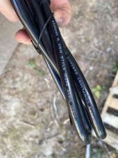
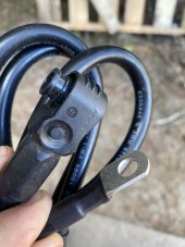
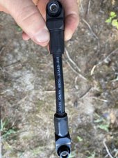
The batteries came with 2 pairs of 6ft 4AWG cables that I had planned to use to connect the bank to the inverters, but I believe these cables are undersized for this purpose. And if I do purchase new cables to run from the battery bank to the inverters, does anyone know where to purchase the quick connect fittings I would need to attach that new larger cable to the Pytes battery quick connect battery lugs?

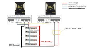
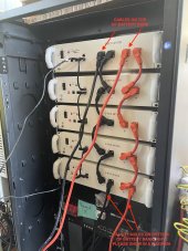
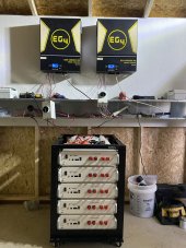
Here are two photos. The one with the wiring is the image I was shown before we bought the 5 Pytes batteries. The other image is a picture of our actual setup as it stands right now. Note: PV wiring and disconnects were just wired in to test the inverters and will all be properly placed in the wireway and conduit now that it has been tested.
 

Attachments

  • 48100R project from our customer 2.jpg
    48100R project from our customer 2.jpg
    452.5 KB · Views: 32
  • IMG_8225.JPG
    IMG_8225.JPG
    189.8 KB · Views: 33
In your battery bank, typically you want to have the positive connection on one end of your batteries and the negative connection on the other end of your batteries to allow for equal power distribution.

As far as the image, the only reason why I could think they have another set of cables added on was to daisy chain another battery/rack (but most server rack batteries have a max number of batteries that can be strung together in parallel).

I would also agree that the 4AWG seems small for the connection to the inverters. What's the temp rating on the side of the cable?
 
Thanks for the insight, Adam. I'll find out what the temperature rating is on those 72" battery to inverter cables and post it to this thread soon.

Aside from the cable size, it would seem that a good way to connect our battery bank to the two separate inverters would be to take the + cable from the top battery and the - cable from the bottom battery and connect those to Inverter #1; then connect the - cable from the top battery and the + cable from the bottom battery and connect that pair to Inverter #2. Then there would be no need for any busbars in the system, at least according to my logic (again I admit I have very little experience on this topic).

Also, what stumps me is why it is that the 6" 4AWG jumper cables between each battery would be correctly sized (otherwise why would they include those in the 5 battery kit), but the 72" battery --> inverter cables would not be correctly sized. Won't both of those cables (the short jumper cables and the longer battery to inverter cables) be carrying the same current at any given time? Very confusing to me.
 
Aside from the cable size, it would seem that a good way to connect our battery bank to the two separate inverters would be to take the + cable from the top battery and the - cable from the bottom battery and connect those to Inverter #1; then connect the - cable from the top battery and the + cable from the bottom battery and connect that pair to Inverter #2. Then there would be no need for any busbars in the system, at least according to my logic (again I admit I have very little experience on this topic).
I can't say that I've ever seen it done that way. It might work in theory, but you still need some kind of over current device between your battery bank and your inverters. That could either be in the form of a class T fuse on the positive side and/or 200a DC rated circuit breakers. A fault/short could do a lot of damage with the amount of current those batteries can output.

Also, what stumps me is why it is that the 6" 4AWG jumper cables between each battery would be correctly sized (otherwise why would they include those in the 5 battery kit), but the 72" battery --> inverter cables would not be correctly sized. Won't both of those cables (the short jumper cables and the longer battery to inverter cables) be carrying the same current at any given time? Very confusing to me.
From my limited understanding, cable current rating is based on the gauge, temp rating, length of cable and the type of shielding used on on the cable.
 
Adam is exactly right. The other factor is the inverters rating. At 13,000 watts of potential output you can pull a lot from the battery bank. Depending on the temp rating, usually 60c/75c/or 90c, you might potentially need 4/0 instead of 4AWG.
 
I can't say that I've ever seen it done that way. It might work in theory, but you still need some kind of over current device between your battery bank and your inverters. That could either be in the form of a class T fuse on the positive side and/or 200a DC rated circuit breakers. A fault/short could do a lot of damage with the amount of current those batteries can output.
Thanks Adam. Agreed on the over current device--I have a 200a DC rated breaker that will be on the positive leg of each battery-->inverter cable, so one for each inverter, and each mounted inside an individual breaker box.
From my limited understanding, cable current rating is based on the gauge, temp rating, length of cable and the type of shielding used on on the cable.
Ah that's interesting. Here are the photos of the cables that shipped to me with the Pytes batteries. They are 4AWG, 1,000v, are AWM style and have a 105℃ rating.
 

Attachments

  • IMG_8234.JPG
    IMG_8234.JPG
    130.5 KB · Views: 5
  • IMG_8235.JPG
    IMG_8235.JPG
    129.2 KB · Views: 5
  • IMG_8236.JPG
    IMG_8236.JPG
    148 KB · Views: 5
Adam is exactly right. The other factor is the inverters rating. At 13,000 watts of potential output you can pull a lot from the battery bank. Depending on the temp rating, usually 60c/75c/or 90c, you might potentially need 4/0 instead of 4AWG.
Thanks, SolarPower. I'm curious how just one of those cables that run from the battery to the inverter (as described above to Adam) could end up needing to carry 13,000w. Wouldn't a single positive/negative pair of cables from the battery to the inverter only ever have to carry a maximum of 6,500w?
 
I'm also just having some more thoughts on the cable sizing. Would this be the correct formula to determine cable size between the battery bank and the inverter, assuming my setup was similar to this (but without the busbars--I don't have those and my server rack isn't designed for one)?

Inverter specs: EG6500EX efficiency rating of 91%
Max current = (6,500w / .91) / 48v = 148.8A

Also, for the shorter jumper cables (in this example they go between each battery and the busbar), why would it be acceptable for those to be 4AWG, when the longer cables between the bus bar and the inverter would need to be thicker (perhaps 2/0 AWG)? It seems that those should be the thickness, no? Or perhaps the length of that cable going from the battery bank to the inverter makes a big difference? I'm just thinking out loud here on this, so I very well could be missing something obvious. Hoping someone can chime in on what that may be. :)
 

Attachments

  • Pytes system.jpg
    Pytes system.jpg
    81.6 KB · Views: 18
You have to keep in mind that you have 2 inverters. Each inverter can charge up to 120A into the battery bank, so if you look at both inverters and add some padding you could be up close to 300a going into the batteries. The calculators that I looked at had a max temp rating of 90 deg C, and they stated you should use 2/0 cable.

If it was me, I would look for 2/0 at a minimum. From what I've seen across the forum, many people that have a rack full of batteries just go straight for the 4/0.
Gotcha, thanks Adam. Two more questions on this if you don't mind sharing your thoughts:

  1. Any idea if there is someplace that can make these wires for me with one end having a lug attachment for the inverter (and DC breaker) and the other end having the Pytes-style quick connect end?
  2. Do you know why the small 6" cables seem to be acceptable to link in between the batteries (or from the battery to the busbar, if I end up needing to go with a busbar setup), whereas it sounds like I should go with either 4/0AWG or 2/0AWG cable from the battery bank to the inverter? Those cables seem as though they would both need to carry the same current.
 
Any idea if there is someplace that can make these wires for me with one end having a lug attachment for the inverter (and DC breaker) and the other end having the Pytes-style quick connect end?
I'm sure there is, but I can't think of where. Can you check with the distributor where you got the batteries?
Do you know why the small 6" cables seem to be acceptable to link in between the batteries (or from the battery to the busbar, if I end up needing to go with a busbar setup), whereas it sounds like I should go with either 4/0AWG or 2/0AWG cable from the battery bank to the inverter? Those cables seem as though they would both need to carry the same current.
I'm guessing it just has to do with the higher temp rating and the shorter distance.
 
I'm sure there is, but I can't think of where. Can you check with the distributor where you got the batteries?
I reached out a few times but didn't get any answer, which is what brought me to putting up these questions on the forum.
I'm guessing it just has to do with the higher temp rating and the shorter distance.
Yes that makes sense. Thanks, Adam.

Btw, how do you like the solar tracking software that you use(d) for your 6500ex setup? Great info in your YT videos, it's very helpful watching someone else with experience on a similar setup.
 
Your welcome!

Solar Assistant is awesome! So much better than the WatchPower software that comes with the inverters.
 
Your welcome!

Solar Assistant is awesome! So much better than the WatchPower software that comes with the inverters.
Great, I'm going to check it out then. Not sure if they/you do affiliate links but if so feel free to send yours over to me to use. I appreciate the assistance today, Adam. (y)
 
I'm also just having some more thoughts on the cable sizing. Would this be the correct formula to determine cable size between the battery bank and the inverter, assuming my setup was similar to this (but without the busbars--I don't have those and my server rack isn't designed for one)?

Inverter specs: EG6500EX efficiency rating of 91%
Max current = (6,500w / .91) / 48v = 148.8A

Also, for the shorter jumper cables (in this example they go between each battery and the busbar), why would it be acceptable for those to be 4AWG, when the longer cables between the bus bar and the inverter would need to be thicker (perhaps 2/0 AWG)? It seems that those should be the thickness, no? Or perhaps the length of that cable going from the battery bank to the inverter makes a big difference? I'm just thinking out loud here on this, so I very well could be missing something obvious. Hoping someone can chime in on what that may be. :)

The reason the short smaller cable works between the batteries and bus bars is it's only carrying the current for that battery, when you now go from bus bar to inverter it is carrying all the current from all the batteries.. Big difference.

I have 20- batteries and use the small jumper wire from all the batteries to bus bars. But i use a 4/0 cable from bus bars to inverters.
 
Back
Top