Hi everyone,
Situation:
I am currently working on extending my 16s 280Ah system.
The current setup is supervised by a Batrium which controls the main relay and cooling, pre-charge control and the main fuses (big old Siemens NH 160A) are operated manually and the entire battery bank is connected to a Sunny Island inverter.
The system runs in self-consumption mode only (i.e. no backup power) and is fed by about 9kWp PV Power which is also connected to two wallboxes, one OpenWB and one "dumb" one.
So far everything runs seamlessly and the self-consumption rate with the battery and PV - controlled charging through the OpenWB is simply amazing.
Extension:
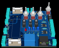
I have already ordered the additional 32 280Ah cells to extend my system and designed a very simple PCB (image attached) to simplify the wiring.
The PCB will handle the 12V Power distribution to the Batrium, cooling system, main and pre-charge relay as well as house the CAN interface.
Questions:
Step 1:
What way have you chosen to go about paralleling cells when extending your battery or putting multiple cells in parallel? I have considered the following options:
1. Just buy additional cell monitors for the Batrium and protect each 16S pack with a fuse before paralleling them. While this provides individual cell monitoring, I would much rather parallel the individual cells to even out any capacity imbalances and I also quite frankly see the point in paying an additional $700 just for cell monitors seeing that they have increased in price by 50% since my last order.
2. Connecting wires (unprotected) to each terminal and a central collecting point to parallel them and connected the cell monitors/ BMS on the connecting point. This would be similar to just using the standard bus bars (which is not an option for me, as the first 16s pack already exists in a compressed fashion). This is an option, but should a single cell in one pack fail/ lag, it will drain the other two cells without giving me a clear indication of what is going on.
3. Similar to option two, but each wire gets a fuse to prevent excessive balancing currents should one cell fail (i.e. the other two wouldn't drain in an attempt to compensate). I like this option, but then I lose the BMS monitoring over that cell and the packs in parallel would be pulled down until the individual pack fuse trips. Thus, this is probably a more dangerous option compared to option 2.
4. Design a PCB that realizes option 3, but includes a continuity measurement on each fuse (i.e. checks periodically if a fuse has blown) and if so, sends a critical fault signal to the BMS shutting down the inverter operations and opening the main relay. This option is preferable to me - has anyone attempted something similar or knows of an IC able to do continuity checks on multiple fuses/ traces/ components at once?
5. Any other ideas?
Step 2:
Does anyone have any experience running a Sunny Island or similar inverter with an automatic transfer switch in Europe?
Happy for any suggestions.
Situation:
I am currently working on extending my 16s 280Ah system.
The current setup is supervised by a Batrium which controls the main relay and cooling, pre-charge control and the main fuses (big old Siemens NH 160A) are operated manually and the entire battery bank is connected to a Sunny Island inverter.
The system runs in self-consumption mode only (i.e. no backup power) and is fed by about 9kWp PV Power which is also connected to two wallboxes, one OpenWB and one "dumb" one.
So far everything runs seamlessly and the self-consumption rate with the battery and PV - controlled charging through the OpenWB is simply amazing.
Extension:
I have already ordered the additional 32 280Ah cells to extend my system and designed a very simple PCB (image attached) to simplify the wiring.
The PCB will handle the 12V Power distribution to the Batrium, cooling system, main and pre-charge relay as well as house the CAN interface.
Questions:
Step 1:
What way have you chosen to go about paralleling cells when extending your battery or putting multiple cells in parallel? I have considered the following options:
1. Just buy additional cell monitors for the Batrium and protect each 16S pack with a fuse before paralleling them. While this provides individual cell monitoring, I would much rather parallel the individual cells to even out any capacity imbalances and I also quite frankly see the point in paying an additional $700 just for cell monitors seeing that they have increased in price by 50% since my last order.
2. Connecting wires (unprotected) to each terminal and a central collecting point to parallel them and connected the cell monitors/ BMS on the connecting point. This would be similar to just using the standard bus bars (which is not an option for me, as the first 16s pack already exists in a compressed fashion). This is an option, but should a single cell in one pack fail/ lag, it will drain the other two cells without giving me a clear indication of what is going on.
3. Similar to option two, but each wire gets a fuse to prevent excessive balancing currents should one cell fail (i.e. the other two wouldn't drain in an attempt to compensate). I like this option, but then I lose the BMS monitoring over that cell and the packs in parallel would be pulled down until the individual pack fuse trips. Thus, this is probably a more dangerous option compared to option 2.
4. Design a PCB that realizes option 3, but includes a continuity measurement on each fuse (i.e. checks periodically if a fuse has blown) and if so, sends a critical fault signal to the BMS shutting down the inverter operations and opening the main relay. This option is preferable to me - has anyone attempted something similar or knows of an IC able to do continuity checks on multiple fuses/ traces/ components at once?
5. Any other ideas?
Step 2:
Does anyone have any experience running a Sunny Island or similar inverter with an automatic transfer switch in Europe?
Happy for any suggestions.