diy solar

diy solar

Best voltage to work with long distance

cyberwombat

New Member
Joined
Aug 22, 2022
Messages
15
Location
Flagstaff, AZ
So my solar array will need to be 150 or so feet from cabin. I'm trying to figure out what the most cost effective solution will be. My system will look like:

- 4 x 270Ah 12V LioFePO4 Batteries
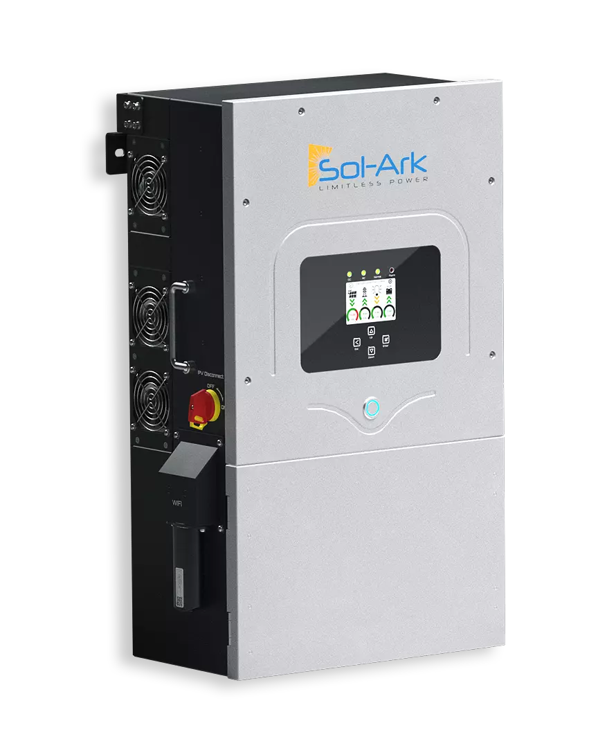
- SA-8K-N Inverter/Charger, Sol-Ark 8K 120/240V-3P
- 24 x 200W 24V PV
Link to SolArk
My house will only need 120 but I need to run cable. I use 40ft solar cables now so can perhaps shorten distance to 100-120. Does it make more sense to keep at 240 coming from Sol-Ark and then step down to 120 or just stay at 120. Not totally sure what size cable I am dealing with yet for this - getting a little conflicting info on NEC codes etc. Ive been looking at step down transformers and they seem pretty affordable but perhaps the extra complexity doesn't make sense?
 
Where is the Sol-Ark being mounted? Normally you would run cable from the solar array to the cabin, where the Sol-Ark would be.
 
So my solar array will need to be 150 or so feet from cabin. I'm trying to figure out what the most cost effective solution will be. My system will look like:

- 4 x 270Ah 12V LioFePO4 Batteries
- SA-8K-N Inverter/Charger, Sol-Ark 8K 120/240V-3P
- 24 x 200W 24V PV
Link to SolArk
My house will only need 120 but I need to run cable. I use 40ft solar cables now so can perhaps shorten distance to 100-120. Does it make more sense to keep at 240 coming from Sol-Ark and then step down to 120 or just stay at 120. Not totally sure what size cable I am dealing with yet for this - getting a little conflicting info on NEC codes etc. Ive been looking at step down transformers and they seem pretty affordable but perhaps the extra complexity doesn't make sense?
Higher voltage for longer distance is always better, right?

Couple weird things:

- No need to step down, just convert your house panel to 120/240. Or is there a weird situation in your panel/system? IE you have a 120V generator that feeds into that panel so it needs both line legs bonded together. In any case even if you for some reason need to step down you might as well do it at the cabin.
- You probably have to add a balancer for that manually assembled 48V pack built from 4 12V. Up for it?
- 200W panels: more racking and wiring than 400W
- if you can run DC above 240V then you can probably drop the cable size. Save money. And then put the SolArk at the cabin. One reason to put it in the middle might be if you want 120/240 distributed to two places and you want to split the difference by putting inverter in the middle

Cable size is pretty predictable if you provide panel specs and string config
 
So my solar array will need to be 150 or so feet from cabin. I'm trying to figure out what the most cost effective solution will be. My system will look like:

- 4 x 270Ah 12V LioFePO4 Batteries
- SA-8K-N Inverter/Charger, Sol-Ark 8K 120/240V-3P
- 24 x 200W 24V PV
Link to SolArk
My house will only need 120 but I need to run cable. I use 40ft solar cables now so can perhaps shorten distance to 100-120. Does it make more sense to keep at 240 coming from Sol-Ark and then step down to 120 or just stay at 120. Not totally sure what size cable I am dealing with yet for this - getting a little conflicting info on NEC codes etc. Ive been looking at step down transformers and they seem pretty affordable but perhaps the extra complexity doesn't make sense?

Yeah, like Zanydroid said, just mount the Solark in the cabin, the Solark 8k can handle 500v DC on the PV input, so you can wire the panels with more in series, to get your voltage up there in the upper voltage range (don't go over the max 500v, at lowest freezing temperature for your area), then you can run an 10 AWG or even an 8 AWG cable from the panels if you wanted to spend a bit more money for slightly better performance.

Voltage Drop Calculator:

Example (you can play with the exact numbers):

Usually NEC (in AC household installations), say to stay under 3% voltage drop, but lower is fine, just means even better performance if you wanted to go more extreme than 10 AWG and use 8 AWG cable... Most people would just use 10 AWG, I'm a little extreme, I like to bump up a gauge fatter than what I need...


How to figure out how many panels can be wired in series, and not go over 500v on Voc, when at coldest temperature (calculator is located about 2/3 the way down page):

Use the panel specs off your solar panel stickers, or the specs sheet to get Temp Coefficient of Voc, and Voc numbers...
 
Last edited:
I guess if your panels are 24v (need to check exact Voc on sticker), but 12 panels in series would be 288v..

So two runs (each 12 panels on their own run) would somewhere around this (per run):

What is the Isc (short-circuit amperage) on the panel sticker? Also the Voc (volts open circuit)? Can you make two sets of wire runs, or would you want to parallel each of the 2 strings of 12 panels (12s2p), and run a single set of wires? It depends on if two strings Isc stays under 18a, or the inverter would clip output at 18a...

Voltage appends in series where amps stays the same, and amps appends in parallel where voltage stays the same... So two strings of 12 panels on each string, paralleled together will double the amps, so if that number is still below 18a (max amps the Solark 8k will use), then you could put all 24 panels on one wire run without losing any power potential.
 
Last edited:
Where is the Sol-Ark being mounted? Normally you would run cable from the solar array to the cabin, where the Sol-Ark would be.
My thoughts are to have the batteries and solark in a shed near the array then run AC from there to the house. Am open to alternatives - i.e batteries and solark in house (currently getting permitted for house build - next year they wont allow that). But that means 150ft of PV cable - isn;t that less efficient? My PVs are wired to output 48V. The actual number I will have is not set - my issue is that I live in the forest and in winter I dont get enough sun so moving panels to a clearing and this winter will get a better idea of input using my current 8x200w panels.
 
I guess if your panels are 24v (need to check exact Voc on sticker), but 12 panels in series would be 288v..

So two runs (each 12 panels on their own run) would somewhere around this (per run):

What is the Isc (short-circuit amperage) on the panel sticker? Also the Voc (volts open circuit)? Can you make two sets of wire runs, or would you want to parallel each of the 2 strings of 12 panels (12s2p), and run a single set of wires? It depends on if two strings Isc stays under 18a, or the inverter would clip output at 18a...

Voltage appends in series where amps stays the same, and amps appends in parallel where voltage stays the same... So two strings of 12 panels on each string, paralleled together will double the amps, so if that number is still below 18a (max amps the Solark 8k will use), then you could put all 24 panels on one wire run without losing any power potential.
Here's the sticker info . Currently wired in 48V output and was plannimg the same once I expanded.
 
Yeah, like Zanydroid said, just mount the Solark in the cabin, the Solark 8k can handle 500v DC on the PV input, so you can wire the panels with more in series, to get your voltage up there in the upper voltage range (don't go over the max 500v, at lowest freezing temperature for your area), then you can run an 10 AWG or even an 8 AWG cable from the panels if you wanted to spend a bit more money for slightly better performance.

Voltage Drop Calculator:

Example (you can play with the exact numbers):

Usually NEC (in AC household installations), say to stay under 3% voltage drop, but lower is fine, just means even better performance if you wanted to go more extreme than 10 AWG and use 8 AWG cable... Most people would just use 10 AWG, I'm a little extreme, I like to bump up a gauge fatter than what I need...


How to figure out how many panels can be wired in series, and not go over 500v on Voc, when at coldest temperature (calculator is located about 2/3 the way down page):

Use the panel specs off your solar panel stickers, or the specs sheet to get Temp Coefficient of Voc, and Voc numbers...
Here's the solar sticker info. I guess I thought it would be better to run the AC than the solar DC for long distance. Id like the solark in the house actually because I plan on connecting to it to program it as part of my automation. Currently the panels are wired in 48V and I plan to do same once I go to a larger array.
 
I guess I thought it would be better to run the AC than the solar DC for long distance.

No, it's best to run PV long distance, AC short distance.

First reason is PV voltage is higher, so less loss for a given wire gauge ($$$) than AC.
(AC can be sent long distances stepped up to high voltage. Utilities run 12kV to neighborhoods before stepping down.)

Second reason is that AC should be within +/-5% voltage, and IR drop cuts into that. But PV works across a wide range of MPPT voltage. Voltage drop is just power loss, nothing more, unless below minimum MPPT voltage.

Third reason is that losses in PV are greatest when PV production is highest (likely unneeded surplus), and losses are low when production is low and all is needed.

Fourth reason is that AC has to deliver surge power to start motors, 5x operating power, and too much resistance in wires can cause brown out. Designed for 3% max voltage drop, the surge might hit 15% drop. Sure don't want more than that.


And then there is the desire to keep batteries at a comfortable temperature. However, you want to protect the house from fire. So that is a separate issue to work out.
 
With a modern MPPT there is no need to worry about the legacy 12v or 24v panel designation or wiring 2 24v volt series because of 48 volt battery voltage. Using larger panels with a higher voltage is an option, and will be a better match for the sol-ark.

With 24 of those 200w rich solar panels wiring them 12 panels in series will get the voltage up, and limit the effect of voltage drop, and allow you to install the sol-ark the house. Run 5 10awg conductors from the sol-ark at the cabin to the panel location these will provide connection for the 2 strings of panels and a ground. This wire size will keep voltage drop under 2%.
 
Here's the solar sticker info. I guess I thought it would be better to run the AC than the solar DC for long distance. Id like the solark in the house actually because I plan on connecting to it to program it as part of my automation. Currently the panels are wired in 48V and I plan to do same once I go to a larger array.

My thought is always that I'd rather rewire the solar panels for the highest realistic voltage and it have the longer run, since the PV only runs a battery charger (no surge loading), and have the inverter closest to the loads, for less voltage drop, and better surge power available to run startup loads.

There are people who run longer runs than 120ft on PV solar runs, it's all down to the numbers using the voltage drop calculator, and stay within acceptable levels. Also, if you can keep the batteries in the house, then you can maintain them in temp control environment, where they can be warm in the Winter and operate more efficiently. With LFP batteries, you can't charge on them when below freezing temp.
 
My thoughts are to have the batteries and solark in a shed near the array then run AC from there to the house. Am open to alternatives - i.e batteries and solark in house (currently getting permitted for house build - next year they wont allow that). But that means 150ft of PV cable - isn;t that less efficient? My PVs are wired to output 48V. The actual number I will have is not set - my issue is that I live in the forest and in winter I dont get enough sun so moving panels to a clearing and this winter will get a better idea of input using my current 8x200w panels.
Inverter is best where you will use it.
 
2% voltage drop for PV is good, but not at all required. Even 10% or more drop at max current would work, just wastes that much of the power. And only at times of peak current. Compare cost of heavier copper wire to cost of additional panels for same watt hours.

Even 14 awg would work. (Although, single ground wire ought to have ampacity for both strings in parallel, to be completely safe.)

If your array has two strings of different orientations, e.g. SE and SW, they will deliver peak current at different times. Connecting them in parallel works fine, if same length and neither has excessive shading. A field test determined about 2% loss when paralleled vs. separate MPPT. Paralleled, they can share a single pair of home-run wires, making better utilization of it by more hours of good current.

Putting in two pairs now is good, for future expansion of PV. Or for an AC outlet at the other end.
 
With a modern MPPT there is no need to worry about the legacy 12v or 24v panel designation or wiring 2 24v volt series because of 48 volt battery voltage. Using larger panels with a higher voltage is an option, and will be a better match for the sol-ark.

With 24 of those 200w rich solar panels wiring them 12 panels in series will get the voltage up, and limit the effect of voltage drop, and allow you to install the sol-ark the house. Run 5 10awg conductors from the sol-ark at the cabin to the panel location these will provide connection for the 2 strings of panels and a ground. This wire size will keep voltage drop under 2%.
What do you mean exactly by 5 10awg - not 4?
 
For safety regarding AC as well as DC.

 
Couple more things that were confusing about your details

"40 foot solar cable": Does this mean you are using prefabricated cables? Better to just buy a roll of PV and a $50 crimp tool, plus NAME BRAND AND MATCHING MC4 connectors (not the free ones that come with the crimp tool that were probably crap that fell out the back of a factory in China. Nothing against parts from China, they just need to have a proper supply chain and papers). Minimizing splices in PV is best practice because of the danger of DC arc.

(MC4 style connectors must be UL listed to pair with each other, this is code derived from real world problems. You should verify the brand of the MC4 connector on the solar panels and use cables that match).

"Panels wired in 48V". It wouldn't have worked for your 8K because that is lower than MPP minimum voltages. Please be mindful of the MPPT range. In addition to the VOC which will smoke your inverter, you also need to keep the Vmpp (from adding the solar panel voltages) between the MPPT voltage range when temperature compensation is factored in. That means checking both the low temperature and high temperature compensation (low temp = increases voltage, high temp = decreases voltage, the length of the wiring run also decreases voltage). And note the panel temperature is going to be hotter than ambient air.

If you provide the 99% or 99.9% High/Low temp numbers from ASHRAE for your location someone can probably do the calculation for you.

Max DC voltage

MPPT voltage range
500V

150-425V
Starting voltage175V
 
Last edited:
Couple more things that were confusing about your details

"40 foot solar cable": Does this mean you are using prefabricated cables? Better to just buy a roll of PV and a $50 crimp tool, plus NAME BRAND AND MATCHING MC4 connectors (not the free ones that come with the crimp tool that were probably crap that fell out the back of a factory in China. Nothing against parts from China, they just need to have a proper supply chain and papers). Minimizing splices in PV is best practice because of the danger of DC arc.

(MC4 style connectors must be UL listed to pair with each other, this is code derived from real world problems. You should verify the brand of the MC4 connector on the solar panels and use cables that match).

"Panels wired in 48V". It wouldn't have worked for your 8K because that is lower than MPP minimum voltages. Please be mindful of the MPPT range. In addition to the VOC which will smoke your inverter, you also need to keep the Vmpp (from adding the solar panel voltages) between the MPPT voltage range when temperature compensation is factored in. That means checking both the low temperature and high temperature compensation (low temp = increases voltage, high temp = decreases voltage, the length of the wiring run also decreases voltage). And note the panel temperature is going to be hotter than ambient air.

If you provide the 99% or 99.9% High/Low temp numbers from AHRI for your location someone can probably do the calculation for you.

Max DC voltage

MPPT voltage range
500V

150-425V
Starting voltage175V
I checked the crimps on some pre-made MC4 cables that I bought from Amazon years ago and not a single one was crimped properly. Most of the time the wire would just fall straight out of the crimped connector part when I un-screwed the plastic part.
 
Last edited:
Back
Top