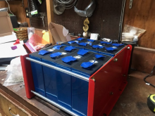
My first pack of prismatic cell will arrive next week. I think I will use Panduit Dura-Ty to compress the cells with plywood of the same size of the cells at both ends. I have used them before for telecommunications work and they are very strong.
You are using an out of date browser. It may not display this or other websites correctly.
You should upgrade or use an alternative browser.
You should upgrade or use an alternative browser.
Best way to compress cells in packs
- Thread starter cypher2001
- Start date
If the cells are to used in a mobile application. They need to be constrained from moving relative to each other. So sufficient clamping so that you cannot move any cell relative to another is required in my view. For stationary applications you don't absolutely need as much restraint, though I would suggest it regardless for various reasons.
Steve_S
Offgrid Cabineer, N.E. Ontario, Canada
The sides & tops are considerably narrower and stronger than the weak "faces". The pressure would have to be severe to have any effect on those surfaces. To reach that level, the cells would have to pushed to, or beyond their capacities and in Energy Storage that really is not a factor unless using really small capacity cells. ESS type systems use 100AH cells or larger, not 20AH or 30AH.Are you not affraid that the cells will swell on the side or top?
Capt Bill
Sailing Options
On my 2nd set of 8x 280 Ah Eve cells; and considering this compression option; I notice the batch I am working on does not have real even planes on the sides. I also notice that when sliding them together, and then running my hand across those sides; I can feel some very slight wavey sides of battery. I am pretty sure my 1st set is similar via hand rubbing across external #1 and #8 side cells. I put my first set of 8 280 Ah cell together with double sided tape between each cell thinking that would be better for keeping em cooler. As I consider compression of my battery bank ... My question is: Is it normal for the side planes of battery not to be a perfect flat plane ???? what do you folks who apply compression notice about that ??? And what is the advantage of compression over air space between them ???recommend that when compressing the cells, that it be done with them at a lower charge 50% is likely the optimal median... When cells are full 3.55V+ they do tend to bloat a bit (normal). This is more pronounced with the Aluminium Cased "blue" cells.
Is 15 in-lb on 4 bolts over the surface of the cell equivalent to 12psi?Do you have a compression force spec for the cells? If not, ballpark 15 in-lb. Which is a not much.
I rigged up a jig like this for single 280Ah cells I am characterizing and am struggling to understand wha torque I should apply to my 4 1/4” bolts to provide 300 kgf (12psi) of clamping force...
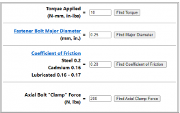
This calculator here will give you a rough idea. 10 in-lb yields 200lb of clamping force. 4x200=800lb, which is a bit high. If you are using nylock nuts you can measure the free drag, but its around 5 in-lb. With nylock nuts that would be 15 in-lb total, 10 effective (approximately, just measure your nuts). With 4x 1/4-20 thread, you would want somewhere between 5-8 in-lb (effective, add locking fastener drag).

Bolt Torque, Axial Clamp Force, Bolt Diameter Calculator
This fastener bolt torque calculator will Estimate the unknown torque, diameter, axial force applied and coefficient of turning friction for the given conditions.
www.engineersedge.com

Steve_S
Offgrid Cabineer, N.E. Ontario, Canada
None of the aluminum cells I've handled were ever perfectly flat. The metal is not that thick, you can squeeze the cells with your fingers and you'll see what I mean.does not have real even planes on the sides.
The KEY CRITICAL things to remember when compressing them, don't go rabid...
- 10,12 psi is more or less a good "hand squeeze pressure" and that's perfect. Think of it more like "Really Snug" as opposed to "Compressed"
- Care that pressure is "flat & even" on the faces and that the corners are not crushed in any way.
- That the sides are not buckled or deformed in any way because there is too much pressure applied.
If the cells are at ambient room temp and haven't just been heavily charged up at max C-Rate they will NOT be expanded, in fact, they may even appear to be slightly concave.
- Warm them up with heavy charge/discharge at higher temps and they will expand a bit...
- Cool them down to 10°C/50°F and they will contract a little.
I've observed this through my own testing processes (unintentionally actually but it was noticeable) and due to the environment afforded to me by having a separate powerhouse in which I can control the temperatures, even within the internal spaces.
TBH, I feel that far too much time has been spent on this particular subject and it has gone around in circles for months in various threads. I mean, seriously, this is a horse that has been beaten to death, buried, dug up, beaten more, reburied, dug up again .... ad infinitum. Simple COMMON SENSE and a touch of critical thinking and it is obvious that this is NOT such a huge complicated deal. It's not flippin Politics EH !
Simple point: Every company that produces "drop-in" or assembled battery packs, to full-on ESS assemblies, ALL bind the LFP cells and for the Prismatics the most common method is by using Strapping like shown in the pictures below. Does anyone think they use some kind of Gauge or Meter to measure the amount of pressure ?
Edit - BTW: Something I mentioned back on MAY 30-2020.

EVE-280 cells should these be clamped tight or spaced for expansion?
I working on my 4s 280ah battery plans. I thinking of my battery box. should these cells have a air space between them or be bonded tight together with a hose clamp or something similar.
Last edited:
Got it - thanks.This calculator here will give you a rough idea. 10 in-lb yields 200lb of clamping force. 4x200=800lb, which is a bit high. If you are using nylock nuts you can measure the free drag, but its around 5 in-lb. With nylock nuts that would be 15 in-lb total, 10 effective (approximately, just measure your nuts). With 4x 1/4-20 thread, you would want somewhere between 5-8 in-lb (effective, add locking fastener drag).
Bolt Torque, Axial Clamp Force, Bolt Diameter Calculator
This fastener bolt torque calculator will Estimate the unknown torque, diameter, axial force applied and coefficient of turning friction for the given conditions.www.engineersedge.com
View attachment 32262
So if using just a standard stainless nut rather than nylock you’d want about 10 in-lbs of torque and if aiming for exactly 300kgf (660 lbs) you’d want 8.25 in-lbs, correct?
I’m using 4 standard 1/4” stainless bolts but didn’t pay attention to whether they were 1/4-20 or some other thread pitch - I don’t see any entry for thread pitch in the calculator, so is that a factor or not?
Yeah, tell me about it.Pitch matters, but at these low of torques its not significant.
With 4 x 1/4" fasteners, I would go 8 in-lb as stated above. Its not a lot of torque.
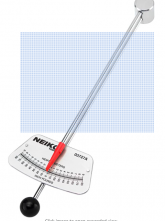
My torque-wrench goes to 600 in-lbs with it’s finest increment at 25 in-lbs. Looks like I’ll need to get a finer-torque wrench if I want to get into this 300kgf LiFePO4 fixture game...
I just weighed my torque-wrench and the handle-end weighs 0.5lbs when the drive side is supported and that handle is exactly 12” long.
If the full 0.5lbs was position at the end of the handle, I think that translates to 6 in-lbs when the handle stops rotating under it’s own weight and comes to rest at 90-degrees (horizontal).
That 0.5 lbs is distributed along the handle with more of the weight near the end (due to the gauge) but I believe that means there is at least 3 in-lbs of torque from supporting the weight of the torque wrench horizontally.
So I believe I have a cheap and easy way to apply 3-6 in-lbs of torque (~4.5 to 9psi) which will probably constitute my first attempt at this LiFePO4 ‘fixture’ game...
Thanks. Once I decide clamping to 12psi is definitely the way I want to go, I’ll pick up one of those.
For just screwing around with a few charge/discharge cycles while characterizing, I think my cheap and easy path of ‘letting the handle apply minimum torque through it’s weight and length’ should be close enough for jazz...
Very nice! Have you performed any tests yet?Here is a prototype with bent steel plates and rods. Rubber pads at the ends, and eventually coil springs. If it tests well we might put together a convenient hardware kit.
View attachment 32355
length and psi of force at 100%, 50% and 0% SOC? (Full, half-full and empty)
It hasn't been tested yet. That being said, once the springs are installed, the clamping force will be within 10% of the theoretical for any SOC. So I see no reason to go full instrumentation. This isn't rocket science. The primary purpose of this fixture is to secure the pack for rough mobile applications. Longevity is a secondary goal.
Yeah, no need for precision instrumentation.It hasn't been tested yet. That being said, once the springs are installed, the clamping force will be within 10% of the theoretical for any SOC. So I see no reason to go full instrumentation. This isn't rocket science. The primary purpose of this fixture is to secure the pack for rough mobile applications. Longevity is a secondary goal.
I’m primarily interested in mechanical stretch at the extremes (stress on the terminals). That just needs a ruler to check (how much longer is the top surface of the pack at 100% that at 50%
And the only other thing that matters is approximate pounds of force or PSI at the midpoint and both extremes of charge (which you should be able to check with your torque wrench).
When do you anticipate starting first charge/discharge cycles on the cells in the fixture?
When do you anticipate starting first charge/discharge cycles on the cells in the fixture?
I can't say. This is being built by an associate of mine (across the country from me) using some parts we collaborated on.
As far as bus bars go, I don't recommend the solid type for mobile applications.
Clamping load is going to be determined by spring compression. It will be set at 100% SOC currently (to 12psi plus/minus 1psi). As the cell shrinks during discharge this will drop to no lower than 8psi. I suspect it will be between 9-13psi under all conditions, as the supplied values for expansion of the cells are fairly conservative.
Bob B
Emperor Of Solar
- Joined
- Sep 21, 2019
- Messages
- 8,652
Can you please post pictures and details over here after you get a completed version?I can't say. This is being build by an associate of mine (across the country from me) using some parts we collaborated on.
As far as bus bars go, I don't recommend the solid type for mobile applications.
Clamping load is going to be determined by spring compression. It will be set at 100% SOC currently (to 12psi plus/minus 1psi). As the cell shrinks during discharge this will drop to no lower than 8psi. I suspect it will be between 9-13psi under all conditions, as the supplied values for expansion of the cells are fairly conservative.

Pack / Cell compression Optimized By Using Springs.
I am opening this thread to split it off from the general cell compression thread. That way those looking for info don't have to sort thru a thread that has many paths for pack compression. If you are new to this idea, it stemmed from an EVE cell specification that indicated a significant...
Can you please post pictures and details over here after you get a completed version?

Pack / Cell compression Optimized By Using Springs.
I am opening this thread to split it off from the general cell compression thread. That way those looking for info don't have to sort thru a thread that has many paths for pack compression. If you are new to this idea, it stemmed from an EVE cell specification that indicated a significant...diysolarforum.com
Yeah, no problem.
Similar threads
- Replies
- 16
- Views
- 692
- Replies
- 5
- Views
- 172
- Replies
- 7
- Views
- 314
- Replies
- 1
- Views
- 217
- Replies
- 967
- Views
- 37K


