diy solar

diy solar

BigBatteries with Bus Bar

Living hakuna

New Member
Joined
Nov 25, 2020
Messages
14
Hello,

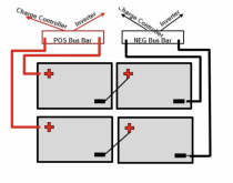
I'm getting 4 24V @170 batteries, connect then in series (48V) and parallel (340Ah).

The batteries from Bigbattery.com use an Andreson 175 connector so to get 3cables in 1 connector is impossible when using (1/0 gauge) cables so I want to know if this is ok to connect using POS/NEG bus bars. This will allow me to have two cables per connector.

Does this configuration look like I will achieve what I am looking for? Please ignore the charge controller from the bus bar it will go directly to the inverter. Screen Shot 2020-12-01 at 10.48.39 PM.png
 
Is this a possible way of connecting the batteries ? is this correct?Screen Shot 2020-12-02 at 12.03.59 AM.png
 
Last edited:
Looks like it.
Match the wire lengths.
I would connect inverter to middle of 3 points on busbar.

Got a fuse?

Is wire to inverter short? you don't want charge controller seeing voltage drops and spikes from inverter's current going through a long wire.
 
One fuse per battery series string positive. If the battery has one integrated, additional is not needed.
 
Looks like it.
Match the wire lengths.
I would connect inverter to middle of 3 points on busbar.

Got a fuse?

Is wire to inverter short? you don't want charge controller seeing voltage drops and spikes from inverter's current going through a long wire.
Hello, when you said match the wire lengths were you referring to the image in post #2? The middle positive to negative cable looks much smaller than all the others. I am having an issue with Anderson connectors where I have 4 24v lifepo4 batteries, 2 in series and then those in parallel. 1 battery in each series is being drained way faster than the other, and eventually the BMS shuts the battery down. If I switch the batteries around in series, it happens to the other battery in the same position.

The only thing I can think of is I have wired them incorrectly with differing cable lengths.

I want to try and wire the as the image in post #2 depicts, but I wanted to be clear on what your comment was referring to. Thanks!
 
Differing cable lengths should only matter at high currents.

While not all wires have to be same length, the path from inverter negative through cables, a series string of cells/batteries, and to inverter positive should the same as the path though any other paralleled batteries. Wire gauge will sometimes be different in different sections, but same length of each gauge used.

With 2 or 4 batteries, lengths of wire shared by multiple paralleled batteries probably just happens. If wiring 3 in parallel, avoid having 1 wire carry the current of two batteries, trying to match a wire carrying current of a single battery. It is IR drop that needs to match.


"1 battery in each series is being drained way faster than the other" ?
"If I switch the batteries around in series, it happens to the other battery in the same position." ???

Two batteries in series have to carry the same current. If one drains first it has less capacity. Swapping them, should happen to same battery, not same position in the string.

Disconnect one paralleled 48V pair to simplify, see if two batteries in series behave differently. Then swap them and check again.

It sounds as though BMS is seeing something different. Do you have a 48V BMS hooked to two 24V batteries, so the cable connecting cells between them shows up as cell voltage? I would expect each "battery", 24V in this case, to have its own BMS. Does the BMS connect to anything outside the battery case, where it could see extra IR drop?
 
I have 4 of the following batteries:

Each has its own BMS. As the OP mentioned, these come with Anderson connectors, and the cables the manufacturer sold me for getting two into parallel included shoving 2 6 guage wires into 1 Anderson terminal, which is not possible with 1/0 wire. What I did was wire two sets in series with Anderson connectors, then have two positive and two negative cables (1 from each series) which I wired straight into the inverter on the negative side, and into a dc cutoff switch on the positive side, followed by a 250 amp fuse and then 1 cable into the positive inverter terminal.

I am guessing this is what is causing my issue. The resistance of two negative cables wired directly into the negative inverter terminal may be doing something wacky, or the 2 positive cables wired onto one terminal in the cutoff switch. If that is not the issue, then it seems there may be something more serious happening.

At any rate, everything is off and unplugged until I figure it out.
Look at this diagram it might help you a little more

We didn't like how you get 3 cables jammed into an Anderson connector so I bought new Anderson connectors on amazon along with 10FT of 1/0 wire and the bus bars and it came out really good.
 

Attachments

  • Screen Shot 2020-12-01 at 10.48.39 PM.png
    Screen Shot 2020-12-01 at 10.48.39 PM.png
    153 KB · Views: 35
  • IMG_6825.JPG
    IMG_6825.JPG
    98.3 KB · Views: 40
Look at this diagram it might help you a little more

We didn't like how you get 3 cables jammed into an Anderson connector so I bought new Anderson connectors on amazon along with 10FT of 1/0 wire and the bus bars and it came out really good.
Thank you, I am going to rewire the Anderson connectors to bus bars next week when the parts arrive. Hopefully this solves my issue!
 
Look at this diagram it might help you a little more

We didn't like how you get 3 cables jammed into an Anderson connector so I bought new Anderson connectors on amazon along with 10FT of 1/0 wire and the bus bars and it came out really good.
I have two 12v, 120ah from BatteryEvo (300 amp internal fuse) using the SB175 parallel 6awg cable going into a 1200/2400w Giandel PSW inverter. I was told the 6awg is too small for the inverter. The ABYC app indicates I need 2/0 cable so I bought 5 feet of black and red and two SB175 connectors with 1/0 lugs. The 2/0 fits into the lugs. Waiting for 250amp 4-bolt bus bars to arrive before my workout with the pneumatic crimper. Just realized I may not have large enough ring-connectors.

I have a 40amp solar charge controller. Should the battery cables go on the first and last posts of the bus bar with the SCC and inverter in the middle? Thanks in advance.
 
Yes, I would do something like that.

12V 2400W is approximately 200A, less than 250A busbar so it shouldn't be overloaded even if both batteries fed from one end.
Putting one battery connection on either side of inverter splits the current, 100A each way, which is better.

4-bolt, I might put batteries on bolt #1 and #3 and inverter then SCC on bolt #2. That would be perfect symmetry, although having one battery on #4 instead of #3 might not be different enough to matter.

If the busbars have bolts through rather than studs, you might put inverter on one side and SCC on other.
They are studs not bolts. Sorry for the bad description. So the better setup is batteries on #1 and #3 with SCC and inverter on #2?

I'll be running a 200 amp ANL inline fuse from the bus bar to the inverter. My inverter is rated at 40 amps so I'll be running a 40 amp ANL inline fuse to the bus bar. Is there anything else I'm missing? Thanks in advance.
 
SCC rated 40 amps? Then use a 50A fuse, and a wire of sufficient ampacity (8 awg). 25% larger avoids nuisance blowing.

2400W inverter on 12V? that's nominally 200A, so fuse needs to be larger.

Low voltage can be below 12V, assume 10V.

What is the efficiency of inverter at 100% load? Likely not the "peak efficiency", if that's all they list. I'll assume 90%
We want fuse 25% larger than maximum continuous load, to avoid nuisance trips.

My measurement and math say that an inverter draws pulses of current from the battery, because its output is a sine wave.
Same power delivered, but not continuously. This heats the wires and fuse more. I came up with 12% extra for that.


2400W/10V /0.9 x 1.25 x 1.12 = 373A

So I would suggest a 400A fuse and wire of sufficient ampacity. Or at least 350A.

I use class T fuse, which is rated 20,000A interrupting. That's enough for what I think a lithium battery can deliver. Perhaps the fuses in your batteries are already good enough, but I have to wonder. I doubt the fuse ratings actually exceed what the battery could deliver, but they've probably tested the pack into a short circuit.
 
Back
Top