Rope103
New Member
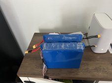
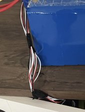
This will be my first battery/ solar power station I have ever built and want to get some input to make sure this will work before I buy everything and it blows up in my face. Please let me know if this plan is dangerous, especially connecting the split wires together. These 2 batteries are from 2 almost new identical power stations that I fried the circuits on, both still have a voltage of around 13-13.5 volts so I assume they still work. 

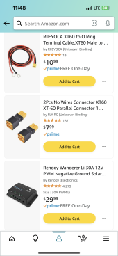
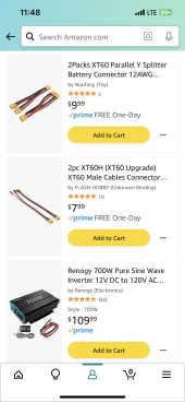
 The plan is to connect these two 500 wh LiFePO4 batteries together in parallel using the xt60 parallel connectors connected to the two reds and 2 black xt60s. Then connect the Y splitter connectors to each side. Then take the XT60 male to banana and cut off the banana ends and strip some of the wire to expose it. Then twist the red and black together on the separate cables turning the 4 wire into 2, one coming from the original black wires and red wire from the battery. Then I will connect these twisted wires to my renogy 10A charge controller(I know my photo has a 30A, I’m using a 10A). Now back to the other 2 unused wires on the Y splitter. On each one I will connect an xt60 to O ring connector and then connect those to the 700W pure sine inverter. Like the charge controller I will have four wire (2 red 2 black) so I will connect the red and black to each other to create 2 O rings that I can connect to the inverter. The solar input will be a 100watt solar panel. (yes I do understand that doing it this way will make solar charging the only way to charge the battery.)


 The plan is to connect these two 500 wh LiFePO4 batteries together in parallel using the xt60 parallel connectors connected to the two reds and 2 black xt60s. Then connect the Y splitter connectors to each side. Then take the XT60 male to banana and cut off the banana ends and strip some of the wire to expose it. Then twist the red and black together on the separate cables turning the 4 wire into 2, one coming from the original black wires and red wire from the battery. Then I will connect these twisted wires to my renogy 10A charge controller(I know my photo has a 30A, I’m using a 10A). Now back to the other 2 unused wires on the Y splitter. On each one I will connect an xt60 to O ring connector and then connect those to the 700W pure sine inverter. Like the charge controller I will have four wire (2 red 2 black) so I will connect the red and black to each other to create 2 O rings that I can connect to the inverter. The solar input will be a 100watt solar panel. (yes I do understand that doing it this way will make solar charging the only way to charge the battery.)


