diy solar

diy solar

Building the sickest ® VAWT ever. Brilliant minds unite please!!

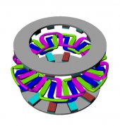
@Hedges I might have found a reason not to make the coil separators from iron filled filament.
My reasoning is that the magnetic flux needs to pass through the coils and having iron filled filament will attract the magnetic field between the coils rather than through them.

Yes, any magnetic core should be through coils, not filling space between them. That space (look at a rotor or stator) just has winding of two adjacent coils, air, varnish.

We either want flux to pass through the center of a coil, and periodically reverse in polarity,
Or given a field with flux going one way, curving, coming back the other way, pass the coil through field edgewise (or move field with coil stationary) so it experiences field first one direction though middle of coil, then the other direction.

That reversing field could be a transformer, no moving parts. Or coil around pole pieces (e.g. one coil on a horseshoe) with bar magnet rotating so each end of horseshoe sees N/S poles alternately.

Or no magnetic material for pole pieces through coil, just field lines passing through coil. But, when field lines go between two coils, that does you no good. With pole pieces providing a low "resistance" path, most of the flux will go through one coil or the next, little between them. Pancake coils, the flux has less chance to go where you don't want it, compared to deep solenoid coils.
yes brother, I think in about 14 days will see some real results.

I'll ask again.. how much to blow up car lights?
 
We know they operate well at 12 to 15V.
I would expect bright and very short lived at 24V

There is "explode", and then there is to actually produce a shock wave, which travels faster than the speed of sound. Even in a solid medium.
It is possible to create a shock wave by applying high voltage (typically stored in a capacitor) through low resistance and low inductance to a small wire. Same thing happens in Arc Blast, where someone shorts out utility grid fed by large transformer in commercial zone. Wire turns to plasma which receives large amount of energy in a short time.

Operating car lights around their intended voltage could make a good test load. Or incandescent home lightbulbs, higher voltage.
I've used oil-filled electric radiators in series or parallel for PV panels and for higher voltage AC.
 
@Warpspeed the above does involve you also quite a bit so please take a stab it it.
The traditional way of building an axial flux machine is to use two flat steel discs with magnets arranged in a circle, with alternative north and south poles facing up.
Two of these disc assemblies face each other, with some very flat coils arranged around in a circle in the resulting air gap between the opposing magnets.

This works very well, there is no cogging, and its very simple, and its all perfectly straightforward.
There is no way of improving on this basic concept.
 
Perhaps I can not improve on the basic concept. I can admit that. But i perhaps can improve on the modularity of the stators. so rather one giant serpentine coil I am opting for 4 smaller ones.

I call it the snake on LSD coil.

1664894151126.png
this way I can install the coils in quarters. easy to make modifications while the turbine and alternator are already installed.
Also now we can already bundle several winds together and weave in the coil even though we are not going in a full circle.
 
three shorted coils :ROFLMAO:

(Yeah, I know. It is just created as a CAD model through symmetry, representing where windings would be. Needs a pair of wire ends from each phase brought out. Those round/flat structures also represent wire bundles.)

Would be convenient to make in segments, as brandnewb mentioned, so they can be placed around existing shaft. Bundles are thick again near the center (and cross each other), so probably need to move magnet disks back for loading.

What's the benefit or tradeoff of two magnet discs, one winding disc, vs. the other way?
 
Like this:
Not like this?

flux-ed.jpg
 
Like this:
that type of axial flux alternator is what I am trying to avoid. because, using my possibly flawed reasoning;
*) coils are less expensive than magnets, so if the goal is to increase voltage with lower rpm, as opposed a typical high rpm alternator, one must not half the magnet field reversal frequency and one must double the coil count. To make things worse the field strength between attracting magnets is not double that of a single pole of a magnet. So we are wasting a lot of magnetic field here.
*) a serpentine coil that goes around the whole perimeter is difficult to maintain in installed alternators that are already attached to a turbine.

Hence I came up with this
1664956358508.png
this alternator can be made in quarters, 8ths, 16th and so forth. and could generate power even with a single element if the others are under maintenance.
Also this alternator uses coils on both sides of the magnets. So no need to half the amount of magnets.

If no blunder has been made I believe this is an improvement over the basic concept. especially over the image you attached as there the coils will suffer from greatly reduced power output as one coil direction is both under influence from a north and south pole at the same time. If I am interpreting things correctly that is. If that is the case than the coil gets stronger field - weaker field to play with and although it does work it will be rather little power.

I think my earlier 14 day prediction for some actual results is still doable.
 
Last edited:
syco!!

I am already planning the drag blades mark II

1664996553317.png
we are looking with the wind direction. as in the wind is coming from our back. Details like springs to pull back open the blades again are not modeled.

if this can work then having 6 blades will be even sweeter.

I am only worried about the noise if the blades will slide over the bended aluminium rods.

So I might not see this to fruition ;(

EDIT; I just figured these blades are susceptible to ice forming and then the whole gliding system will stop working.
 
Last edited:
I am getting excited

I have an early prototype in the making for a full magnet disk traditionally arranged and a quarter of a coil holder.

1665132970271.png

Now the magnet disk it self is not strong enough yet, and not aligning everywhere where they should be, but the interface between those disks and the central column (CC) is rather strong already, even though printed with PLA and not using the m4 45 degrees angled braces yet.

I might end up with the suggestion made here earlier by someone of having the mag disks being held in place on the outer edge by rollers if I can't get cnc milling to work or else.

Because I have been shouting from roof tops that this is going to be sick® I will do 2 tests to see if it ever can be.
Fill up one coil holder quarter with 80 winds of 0.4mm wire (if they fit) that translates to 12 coils of 80 winds each.

Then run a 60 rpm test without the iron powder filled slab and after that run the same test with the iron powder filled. I predict a an increase of a bit over 100% based on my Tesla measurements in both scenario.

If I am not mistaken we can then simply multiply the results by 8 to see what a fully configured alternator would do. If that is correct and results predict car lights can be blown up at 60 rpm then I will see if my dear readers actually want to see that ;)

Otherwise I am going straight to calculating how many winds I need for an output at low rpm that aligns to my 48V battery array (maybe 6 to 12 rpm is my new target, 60 is still far too fast) and then see how large (diam) I can make the coil wires as this disk has a rather large, cough SYCO®, wattage potential it's important not to fry the wires with too much amps.
 
Last edited:
Yesterday was my 1st anniversary here.

Let's see how much damage I can do towards the next ;)
also I am a bit sad. I am not shy to tell.

When I first started here a year ago I was a newb. *cough* still am.

After the cheap Chinese wind turbine debacle thread I knew all that was left is to actually DIY.

When I started this journey I had naive thoughts like. I'll do this in a month maybe a month.1

Boy how this turned out to be a miscalculation ;) I should have known though. I have an IT background and in that realm, when done waterfall, planning is always a challenge.
 
noooooooooooooooooo

80 winds does not fit !!!

1665145702214.png
screw these coil separators. I am printing taller ones. to allow for 80 winds minimum. I mean the mag field boost one gets with powder slabs is insane so a few mm extra tall does not hurt the cause.
 
screw these coil separators. I am printing taller ones. to allow for 80 winds minimum. I mean the mag field boost one gets with powder slabs is insane so a few mm extra tall does not hurt the cause.
screw coil separator fans, for the time being. I am going to try something more flexible figuratively and perhaps also literally
 
that type of axial flux alternator is what I am trying to avoid. because, using my possibly flawed reasoning;
*) coils are less expensive than magnets, so if the goal is to increase voltage with lower rpm, as opposed a typical high rpm alternator, one must not half the magnet field reversal frequency and one must double the coil count. To make things worse the field strength between attracting magnets is not double that of a single pole of a magnet. So we are wasting a lot of magnetic field here.
*) a serpentine coil that goes around the whole perimeter is difficult to maintain in installed alternators that are already attached to a turbine.

Hence I came up with this
View attachment 115050
this alternator can be made in quarters, 8ths, 16th and so forth. and could generate power even with a single element if the others are under maintenance.
Also this alternator uses coils on both sides of the magnets. So no need to half the amount of magnets.

If no blunder has been made I believe this is an improvement over the basic concept. especially over the image you attached as there the coils will suffer from greatly reduced power output as one coil direction is both under influence from a north and south pole at the same time. If I am interpreting things correctly that is. If that is the case than the coil gets stronger field - weaker field to play with and although it does work it will be rather little power.

I think my earlier 14 day prediction for some actual results is still doable.
@Warpspeed at your earliest convenience would you mind stating if my reasoning sounds sound or perhaps you are not certain or I flunked the physics exam?
 
What's the benefit or tradeoff of two magnet discs, one winding disc, vs. the other way?

To answer my own question, it involves the iron or other pole-pieces that duct magnetic field around and back through.

Two magnet discs can be made by bonding magnets to sheets of steel. No moving magnetic field (relative to steel), no eddy currents.

If two winding discs with magnets in between, the magnetic field through coils alternates, so steel discs holding coils would probably get eddy currents and dissipate power.

Brandnewb's coil holder appears to have something troweled in back. Just structural? Or a ferrite mixture? The electrically non-conductive ferrite mixture would serve to duct magnetic field that passed through a coil around and back through another.

But I think metal performs better than powder at low frequency? So the two magnet discs scheme might have a lower "resistance" for the magnetic circuit.

Another idea regarding windings -

Magnetic circuit is through magnets themselves, jumps a gap through air, passes through metal or ferrite, back through air, to another magnet.

Air is the worst magnetic "conductor", so you would like the air gap to be as short a path as possible, and as wide a cross section as possible.

Windings, copper, take up significant thickness. So the opening through center of wire coils is reduced in cross section. If filled with air, that is higher "resistance". If filled with steel/ferrite, a lower "resistance". By using steel/ferrite to duct magnetic field through middle of coil, then fanning out to wide area before jumping the gap, air gap can have as large a cross sectional area as possible. Gap is also as short as possible, with rigid material able to hold its shape, no danger of it bending and contacting rotating magnets.

Here is an example of a (radial configuration) stator. Note pole pieces have a narrow gap to slip in wire while winding coils. The pole pieces are something of a "T" shape, wide area for gap to rotor, small area to allow more winding volume.

1665153358956.png

These coils are also tall, which is OK with pole pieces. Yours will be flat to minimize air gap, but I don't know that you can get enough turns to get the amount of power transfer you want.

For your flat coils disk you may want to encapsulate in epoxy, with a flat surface pressed down as a "mold" to define a rigid flat surface.
 
Back
Top